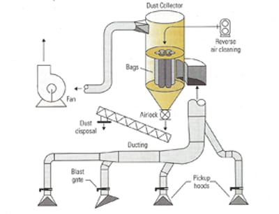
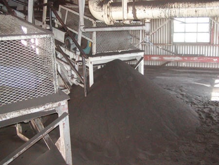
Dust collection systems capture fugitive coal dust that would otherwise escape from the perimeter of equipment areas. Collected fugitive dust is fuel that should be delivered to the furnace and burned (Figure 1). Dust control systems come in many different area-specific configurations. In the typical power plant, they can be found between the coal-unloading station and the outside stockpile, between the coal yard and the crusher station, between the crusher station and the tripper room, and near the coal storage bunker (Figure 2).
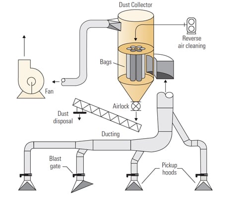
1. A typical coal dust collection system includes pickup hoods, ducting, branch lines, dust collector, fan, and a dust return system. Experience has shown that the pickup hoods and ducting design are more problematic than the fan and dust collector. Source: CDG Engineers
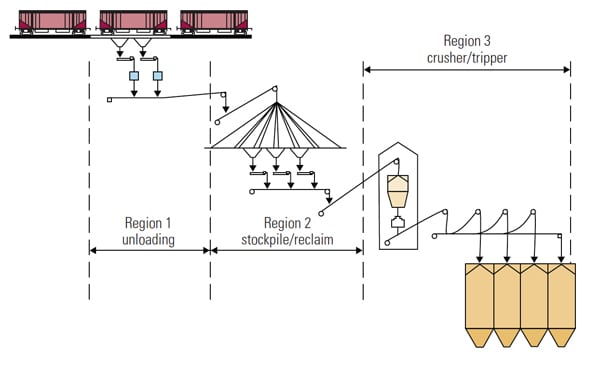
2. Dust control systems come in many different configurations. In a typical power plant, they can be found between the coal-unloading station and the outside stockpile, between the coal yard and the crusher station, between the crusher station and the tripper room, and near the coal storage bunker. Each area has unique dust-control requirements that must met by the use of specific techniques. Source: CDG Engineers
For example, a plant’s railcar-unloading system will usually have a ducted dust collection system, a passive enclosure chamber, or some form of control spray. Coal conveyed to the storage pile typically receives some form of conditioned water spray or surfactant. By contrast, coal from the crushing station contains a higher fraction of fine particulate matter, so it typically calls for a ducted dust collector. Finally, dust from conveyor transfers into the tripper room area is usually controlled by collection hoods and/or by secondary control systems such as fog sprayers.
Dust is ubiquitous in power plants. It can be found at the fan stack, around conveyors, and near coal-transfer stations, where poor or missing seals allow easy escape paths. Conveyor belt cleaners and poor loading areas contribute to material spillage and consequent buildup and dusting. Improperly designed returns from collector hoppers can disperse dust into the environment or feed it back into the dust control circuit. In these cases, the result is a layer of coal dust that accumulates on all horizontal surfaces.
Equipment operating procedures also can cause dusting problems that necessitate excessive maintenance. Too-frequent dust-cleaning cycles can overclean, producing bleeding through collection bags and, potentially, shortened bag life. Undercleaning is just as bad; empty collection bags typically raise the pressure drop across their baghouse, producing lower fan volumes and reduced collection efficiency at pickup hoods.
Dust should not be allowed to accumulate for long periods in the hopper of a dust collector. The dust return system should be sized for peak collection rates and the collected dust either should be conditioned or delivered safely back to the conveying system beyond the collection perimeter. The density of coal dust can be half that of coal, so irregular dumping might be symptomatic of rotary airlock sizing, bridging, or aeration problems. Factors such as moisture, condensation, dew point, and freezing weather also affect the performance of the collection system.
Address the Problem, Not the Symptom
Each piece of equipment that transports or processes coal creates some level of particulate matter. If a piece of equipment is equipped with a containment device, the fine particles that are stirred up cannot escape and can be collected. When there are rapid changes in the direction or speed of equipment motion, fine particles can be carried by air currents through openings and gaps.
The experienced designer will locate pickup hoods and suction points at key points along the coal-delivery route to minimize the escape of dust. System components must be reasonably sealed, and collection hoods must be properly sized and located. For example, when dust is observed streaming from a ducted conveyor transfer point, the most obvious solution would be to provide more suction air at the collection hood. This solution may or may not work, depending on the situation. The leak may indicate that the hood or duct may not be the correct size or be positioned in the best place, or that the equipment generating the dust may not be sealed or contained properly.
Overdrafting collection hoods to solve a dust problem often results in drawing unnecessary coal into the dust collection system without fixing the problem. Adjusting blast gates to redirect air changes the balance of collection ductwork but may create problems elsewhere in the circuit. Remember that a dust collection system is designed to capture only the dust that would otherwise escape to the environment. Obviously, hoods with drafts high enough to pull material off the conveyor belt should be avoided.
Start with an Audit
A dust-control audit can be used to assess the performance of both dust collection and materials handling systems. Determining the performance of a collection system begins with measurements of its airflows and pressures. A water manometer and a series of selected holes in the ductwork are all that is required to map the static pressure of a system. Velocity pressures in ducts are best measured by pitot tubes whose readings reflect the volume of air in the system. Power readings of the collector fan drive should be evaluated against the fan’s performance curve to determine the fan’s optimum operating point. When new filter media are installed and/or a system is rebalanced, performance data should be recorded for later use as a benchmark of future performance. Good recordkeeping provides insights into system trend and can aid in troubleshooting (Figure 3).
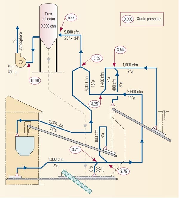
3. A dust-control audit can be used to assess the performance of dust collection and materials-handling systems. Determination of the performance of a collection system begins with measurements of its airflows and pressures. A water manometer is best used to collect static pressure readings. Velocity pressures are measured by pitot tubes and translated to volume flows. Source: CDG Engineers
Evaluations of static pressure readings can quickly identify any problems and deficiencies in the dust control circuit. For example, a high-pressure differential across the baghouse generally means that its filter media are partially blinded. If the differential is normal but the inlet suction is high, that indicates a problem in the ducting circuit. Some ducts may be partially plugged, or some hoods may be blocked completely, forcing higher volumes of air into the remaining ducting.
Likewise, mapping the pressure readings at hood inlets can serve as a quick check of the ducting circuit, although airflow readings would be required for an assessment of the overall system. Blast gates at inlet hood locations are a convenient way to adjust airflows to balance a system, but care must be taken not to optimize one hood and upset the balance of the rest of the system.
High suction pressures have a big impact on collector fan operation. As static pressures go up, fan airflow goes down. Ducting can easily be checked for material buildup by tapping with a hammer and listening. As ducts plug and bags blind, air volumes fall and reduce the performance of the system and the efficiency of dust collection.
Dust 101
Mastering dust control requires a thorough understanding of how dust is generated. Dust is created when fine particulate material becomes separated from the coal stream. Coal received at unloading stations already contains a fair percentage of fine particles. Typically, the fraction of particulate matter passing through 4-mesh (0.187 inch) screens can be as much as 40% or 45% for PRB coals.
As pieces of coal flow through a power plant, they come into contact as a result of feeding, conveying, crushing, and storing. Flowing streams of material interact with the surrounding air through aerodynamic drag forces. For example, material falling from a distance will create air currents along the way. As particles accelerate, the flowing stream expands until the moment of impact. Energy is quickly released and the recompression of the space between the particles creates pressure waves that cause dust clouds to be released. Further complicating the dusting issues, material must also displace an equal amount of air. Other factors affecting dust dispersion include drafts and turbulence from process equipment such as crushers and vibrating feeders.
Where feasible, dust generation can be reduced by limiting the distances that material falls and by minimizing impact forces. For example, conveyors can be slowed down and covered to prevent the effects of cross winds. Material transfer chutes and diverters can be modified to provide better sealing and containment, streamline airflows, and reduce impact.
Coal Containment
The design of belt conveyor transfer chutes recently has become a hot technical topic. Traditional designs discharge material from one conveyor to the next without much consideration of loading zones, impact, or control of the material stream. The operating result has typically been dusting, wear, spillage, noise, and increased maintenance expense. Attempts to add dust collection hoods and other expensive cures at chute inlets and discharges have not really compensated for weaknesses in chute design.
An ideal transfer chute would be a tight enclosure whose target plate smoothly guides discharged material down with a minimum of impact. The downward energy of the material stream is converted to a flow in the direction of the downstream conveyor; this allows the material stream to enter at a shallow angle requiring minimal acceleration to match the speed of the belt. A well-sealed enclosure would also inhibit air from being drawn into the chamber as a result of the induced air generated from the flowing stream. Ample enclosure volume is necessary to allow internal pressure gradients to equalize so the escape of pressurized dust is minimized.
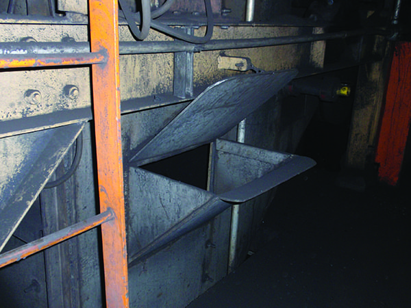
A properly designed transfer chute also would load feed material onto the center of the receiving belt. Off-center conveyor loading is responsible for poor belt tracking and consequent spillage, dusting, and wear at the skirtboard area and throughout the length of the conveyor (Figure 4).

4. A properly designed transfer chute loads material onto the center of the receiving belt. Off-center conveyor loading is responsible for poor belt tracking and consequent spillage, dusting, and wear at the skirtboard area and along the length of the conveyor. Source: CDG Engineers
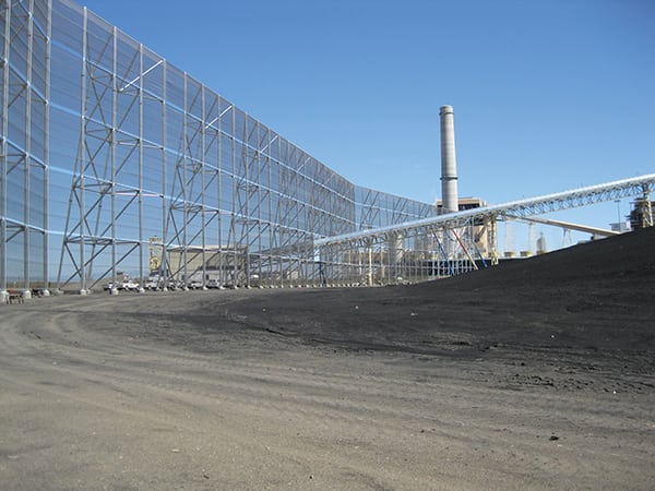
Elsewhere in the system, every attempt should be made to isolate and contain areas where dust is created. Use of better seals at chutes, transfers, and enclosures, and providing shielding or wind screens to prevent drafts all help to prevent the dispersal of dust throughout the plant (Figure 5). Dust should be confined to the areas where it originates and forced back into the product stream. Unloading stations often require better confinement of air currents that are created during dumping cycles. Airborne dust should be given every chance to settle back into the stream.
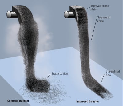
5. Computer models of the basic geometry of transfers can help designers choose the optimum flow rate for a material with a particular particle size distribution. For example, changing the material flow pattern in the chute (left) created a better-guided and a more streamlined pattern with less scatter (right). Source: CDG Engineers
Just Duct It
The single greatest source of problems with dust collection systems is poorly applied or improperly designed ducting and hood arrangements. Handbooks provide guidelines for the quality of vent air required at each dust source, for duct velocity, and for the placement and dimensions of hood pickups. Laying out a system’s ductwork, however, requires skill in arranging trunk and branch lines and suitable junction designs. For example, vertical lines should be preferred to horizontal lines.
The speed at which ducts transport captured dust to the dust collector is important. NFPA Standard 120 states that the minimum acceptable velocity for coal dust is 4,500 feet per minute. Other references cite duct velocity requirements between 4,000 and 5,000 fpm. High duct transport speeds are required to prevent buildup and pluggage. Long horizontal ducts usually require higher velocities, while short vertical runs can be slower. As a practical matter, the sizing of a dust collection system is an economic tradeoff. Its goal is to use the least airflow to make collection effective without requiring excessive fan pressure.
There are many causes of poor ductwork performance. For example, problems can arise when one company designs the system, a second supplies the equipment, and a third builds and installs the ducting. In this case, the performance of the system may be fine initially but falter later when its load peaks or after an upset.
Among the possible solutions to performance problems are adjusting airflow with blast gates, blanking some hoods off, and adding additional hoods and ducting. When new process equipment is added to the plant, additional ducting circuits and/or booster fans may have to be added. Investigations of troubled dust collection systems often reveal that the initial system design was altered due to modifications, deletions, or additions. Corrections become expensive when new dust loads exceed the capacity of installed equipment.
Dust hoods are enclosures that allow fugitive dust to be captured and drawn into a ducted collection system. The proximity of a hood to a source of dust is a key factor for determining its capture velocity. However, the required capture velocity of a hood also is a function of its orientation and the type of dust it captures. Dust hood capture velocities typically range between 200 and 500 fpm. NFPA suggests that hood take-offs have a minimum area of four times the area of the duct. Positioning a hood too close to a source of dust source will result in too much dust (and product) being collected. Pickup effectiveness drops off very quickly as the distance from a hood to a source increases. Where possible, try to position the hoods over rising dust streams.
Shrouding and containment within a dusting environment channel dust to hoods for more effective pickup. Hoods can be extended to provide better capture and guiding of dust streams, but care should be taken not to place hoods too close to interfere with the process. Minimizing the number of hoods and properly placing them is best practice (Figure 6).
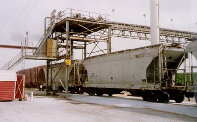
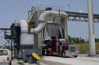
6. At this power plant, severe dusting from a combination railcar/open truck loadout facility handling powdered bulk materials was causing health and safety problems (top). The solution was to design better seals for the belt conveyors and loading spout, and an enclosure to surround the facility and shield it from the wind. Slotted dust collection hoods with pickup hoods were ducted to a dust collector unit and fan mounted outside (bottom). Courtesy: CDG Engineers
Collector Inspector
A dust collector is a steel enclosure containing porous filter media that separate fine dust particles from a flowing stream of dirty air. The most common filter media used in collectors are filter bags and cartridges. Dust particles build up on the outside of the media and form a coating called “dust cake.” It is this layer that does the actual job of filtering fine particles. As the cake builds up, the pressure drop across the filter bag rises. Adjusting the cleaning cycle of the collector so it periodically cleans most of the cake off the filter medium prevents bag blinding. Too-frequent cleaning is bad not only because it contributes to bag wear but also because it can remove all of the dust cake, enabling dust to bleed through. Products for improving flow are commonly used to help pre-coat new bags to provide a uniform coating that shortens the break-in time for efficient collector operation.
The size of the dust collector depends on the system’s required airflow. The quantity of bags or cartridges determines the filtration area and is a function of both the air-to-cloth ratio (expressed in fpm) and the type of dust being collected. For coal dust, the air-to-cloth ratio is typically between 4 and 6 fpm, depending on the concentration of dust loading. The geometry of the collector housing and the number of bags establish the operating parameters of the unit.
The open space between all the bags or cartridges in the housing is the flow area, where the dirty air travels. The average velocity of the air stream through this space is called the “can velocity.” The upper limit of can velocity for coal dusts ranges between 200 and 300 fpm. If it is higher, fine dust purged from bags or cartridges during the cleaning cycle will tend to become re-entrained in the airflow and end up back in them. This phenomenon is most pronounced for collectors with long bags. Because can velocity is directly related to air-to-cloth ratio, choosing a low-cost dust collector with a high air-to-cloth ratio often leads to operating problems.
Bag cleaning methods vary between models and manufacturers, but typically involve reversing the flow of air through the bags. Bags should be visually inspected when there bag cleaning problems are suspected or there is evidence of continual bag blinding. Commercial services are available to evaluate failed filter bags. Analysis could determine whether there is a system problem or a need to switch to a different filter media to better match the dust characteristics.
—Bernard Schonbach is a principal at CDG Engineers. This article was originally published in the October 2003 issue of POWER. Edited by Dr. Robert Peltier, PE.