MECHANICAL
CFB refractory repair
Refractory, the heat-resistant materials that line the inside of most furnaces, are an important component of any steam generator because they protect expensive and vital parts of the generator from thermal shock, caustic chemicals, erosion from slag buildup, damage from falling slag, and catalytic heat. (See "Understanding Refractory Failures," p. 48, for an in-depth look at these phenomena.) Most refractories are more heat-resistant than metals and are needed in parts of the plant where temperatures exceed 1,000F.
According to the Refractories Institute, there are a wide variety of refractory compositions, but they fall into only two categories: brick and fired shapes, and monolithic refractories typically fabricated from plastics, castables, gunning mixes, or ramming mixes. Combinations of both types also are in use.
Although refractories may look like ordinary construction bricks, they are anything but. Refractory designs can have very complex or unusual geometries, and the finished products run the size gamut. Refractory is typically produced from combinations of compounds such as alumina, fireclays, bauxite, chromite, dolomite, magnesite, silicon carbide, and zirconia.
CFBC crucibles
ACC Refractories (Nagpur, Maharashtra), which has provided the refractories of 13 of the 20 circulating fluidized-bed combustion (CFBC) plants in India, notes that CFBC plants are good test sites for analyzing refractory performance because of their high temperatures and caustic chemical environment.
CFBC boilers have had great success in Europe and Japan because of their ability to burn low-grade fuels such as peat, wood waste, and pet coke, as well as hazardous wastes, very efficiently. NOx and SO2 emissions from CFBC plants are low due to the high operating temperature of the boiler. And although the high turbulence of the fluidized bed and the long residence time of coal in the cyclone improve the combustion efficiency of these plants, the high heat and caustic chemicals that are part of the CFBC process can cause refractories to be damaged.
Most of the fuel used in India for power generation is coal, lignite, or pet coke of highly variable quality. In particular, sulfur content can be all over the lot, making it very difficult to adjust feeder concentrations of limestone needed to counter the chemical. If levels of corrosive sulfur oxide gases generated are not kept in check, they can wreak havoc on refractory.
In harsh environments such as these, it is not unusual for refractories to be damaged beyond repair in less than a year. Based on ACC’s experience, the most likely damage in CFBC plants will occur in the bullnose, the kick-off area of the combustor, and the loop seal (Figures 1 to 3). In the bullnose and combustor kick-off areas, the damage is typically due to abrasion; in the loop seal area, the cause is usually thermal shock.
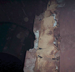
1. Used and abused. This cyclone bullnose refractory in a circulating fluidized-bed combustor boiler has been significantly damaged.
Courtesy: ACC Refractories

2. Worn out. The refractory lining in this combustor kick-off area has experienced considerable erosion due to slag attack, abrasion, and thermal shock.
Courtesy: ACC Refractories
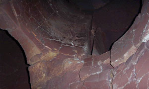
3. Unsealed. The loop seal in this CFBC boiler was damaged by thermal shock. The rapid heating and cooling inherent in CFBC boilers can be very hard on refractories.
Courtesy: ACC Refractories
Damaged goods
The usual culprit in CFBC refractory failures is calcium sulfate, which ACC has found to be the common denominator in all failed castable matrices it has analyzed. Apparently, sulfur prefers to attack the lime-bearing constituents of the castable matrix, which in turn reduces abrasion resistance and increases refractory wear and tear. The table shows which CFBC boiler refractory sections are affected, and why.

Source: ACC Refractories
What causes the damage? Thermal shock—resulting from a rapid change in refractory temperature—can be a big problem in the combustor and loop seal areas of CFBC plants. The area most susceptible to mechanical erosion is the cyclone inlet, where particles may be moving at 80 ft/sec or more and hit the refractory head-on.
Plastic to the rescue
To solve the problem, many CFB plants in India have tried a specially designed, phosphate-bonded aluminous plastic called Accplast 80, and the results have been excellent. Accplast 80 has better physical and thermal properties than typical refractory, and its chemical bonding deters slag from sticking to it. As a result, the refractory resists when slag is dislodged. In addition, Accplast 80 lasts significantly longer—sometimes as much as twice as long—than other refractory materials (Figure 4).

4. Tougher than plastic. Accplast 80—a specially designed, phosphate-bonded aluminous plastic—was used in this resuction duct. After more than two years of service, it is still in excellent condition, showing few signs of wear.
Courtesy: ACC Refractories
"The first thing we had to do was extend the unit’s foundation by 70 inches on both ends to make room for the clutches," says Ron Haglind, a project manager for Great River. "We could do that while the unit was still on-line, since the work didn’t affect the unit’s operation."
The foundation work was completed two weeks before the outage began. Once the turbines were taken off-line, GRE removed the generator enclosure, the exhaust stacks, and the turbines themselves and set them off to the side. Next, engineers reworked the existing foundations to accommodate the clutches and the new turbine positions, including moving all anchor bolts. After installing the clutches, they moved the turbines to their new locations along with the enclosure and the stacks. Aligning the turbines took a few days each.
Most of the outage went according to schedule—except for one unexpected issue at the 26-year-old plant.
"When we took the stacks off, we found there was a lot of corrosion on their metal, so we had to make extensive repairs," says Haglind. "That was a big surprise." Despite the setback, the unit was back on-line only a day behind schedule. Domyahn recommends that anyone doing a similar upgrade inspect the exhaust stacks and inlets ahead of time to avoid any surprises.
Quick payback
With the clutches in place, GRE now uses the turbines to bring the generator up to speed and synchronize it to the grid. At that point, fuel to the turbines is cut off and the clutches disconnect the turbines from the generator. The generator then draws power from the grid to keep turning, meeting the utility’s requirements for spinning reserve. Because the turbines no longer spin 18 hours a day on standby, the TwinPac’s power consumption has dropped by 85%. When peaking power is needed, the turbines fire back up. Once they match speed with the already synchronized generator, the clutches engage and the generator starts providing the needed power.
"By installing the clutches, we took what used to be a seldom-used peaking plant and turned it into a baseload spinning reserve plant that lets us sell an extra 50 MW of very cheap coal-fired electricity," says Domyahn. "The payback has been phenomenal."
However, it isn’t easy to install any phosphate-bonded plastic such as Accplast 80 on a CFBC boiler. One of the biggest challenges is keeping the material in position until it is hardened by heating to 572F. Until it reaches that temperature, Accplast 80 can lose its shape and slump. To prevent that from happening, ACC Refractories recommends holding it in place with ceramic anchors until it hardens.
Following are several other steps that should be taken when installing plastic refractories:
- Provide retainers at predetermined intervals, especially in sloped areas.
- Ensure that any spaces between ceramic anchors are completely filled.
- Equally space the ceramic anchors, use wooden wedges to give them a tight fit, and properly seat the anchors on the support collar to avoid point loading.
- Replace any misaligned anchors.
- Completely fill the shuttering with plastic before placing the next set of forms.
- Remove the shuttering piece by piece after checking for slumping.
- Remember to remove any wooden forms before reheating the boiler.
- Re-ram the plastic after removing the shuttering to ensure that it is properly compacted around anchors.
An ounce of prevention
Attention to maintenance increases the reliability of most power plant equipment, and refractories are no different. During shutdowns, conduct a walk-through and inspect every area protected by refractory. Don’t be troubled by the small gaps you may note around refractory panels; they provide for expansion during reheating.
Accordingly, there’s no need to fill these gaps unless they have widened since the last shutdown. If the gaps have expanded, they should be packed with ceramic fiber to allow for compression during unit startup. Also note gaps around refractory panels that seem too narrow. If they have become packed with ash and/or bed material, the lining may be unable to provide for sufficient thermal expansion.
Finally, check refractory for diagonal cracks that can foster erosion of the material. If cracks have developed and need to be fixed, consider taking the following steps:
- Replace any anchors that have deformed or oxidized.
- Always use at least two anchors per piece of dislodged refractory.
- Remove any old material and replace it with fresh monolithic material. Install this new material without shuttering.
- To repair refractory, try using Accplast 80.
- During every shutdown, clean the expansion joints with compressed air and fill them with a ceramic blanket or wool.
—Contributed by C. Sur, A. Nagar, D.K. Singh, and I.N. Chakraborty, ACC Refractories, India
INSTRUMENTATION
Upgrading conductivity monitoring
Good sampling, monitoring, and analysis of the steam-water cycle are essential for optimizing boiler performance. This is especially true for power plants such as Xcel Energy’s Comanche Station, whose critical-pressure boilers require ultrapure water. At Comanche, conductivity is one of the most important metrics used to characterize water purity, and the accuracy and reliability of conductivity measurements—and operators’ confidence in them—increasingly depend on high- performance on-line instrumentation.
Comanche Station (Figure 5), southeast of Pueblo, Colo., has two units with a combined capacity of 700 MW. Both units burn low-sulfur Powder River Basin coal. Comanche uses about 10,000 acre-feet of water each year to cool equipment and produce steam.
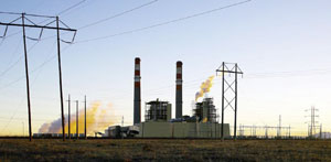
5. Purer than what most folks drink. Xcel Energy’s Comanche Station, a two-unit, 700-MW coal-fired plant southeast of Pueblo, Colo., recently upgraded its water conductivity monitors.
Courtesy: Hach Co.
The steam is supplied by two boilers, each generating 2.5 million lb/hr of steam at 2,500 psi and 1,000F, with an economizer inlet temperature of 480F. The source of makeup water for steam is surface water from the Pueblo Reservoir. Raw water is treated by clarification, cold-lime softening, and filtration through reverse osmosis.
Critical metrics
Conductivity of boiler water must be no more than 50 micromhos/cm, or microsiemens per centimeter (µS/cm). "That’s the absolute maximum," says Dennis Kendall, system chemist for Comanche Station. "We don’t like to get even close to that level." Kendall says the critical proxy for steam quality, however, is cation conductivity, which is limited to 0.3 micromhos per centimeter (or µS/cm) at the exits of the boiler feedwater and condensate pumps (Figure 6). "This is to avoid water quality conditions in which contaminants volatize into the steam and carry over into the turbine, creating O&M problems."
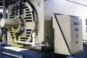
6. Squeaky clean. At Comanche Station, cation conductivity is limited to 0.3 micromhos per centimeter at the exits of the boiler feedwater and condensate pumps. Maintaining this low level minimizes the carryover of contaminants into the steam turbine.
Courtesy: Hach Co.
Monitoring cation conductivity is also an effective way to detect even minor condenser leaks. Because such leaks can quickly deplete boiler water of phosphate, on-line conductivity monitoring is one of the most important parts of the plant’s water-chemistry regime. In addition, Comanche Station’s all-volatile treatment program—which uses hydrazine to control pH and residual oxygen—relies heavily on reliable and accurate measurements of cation conductivity.
End-to-end monitoring of both boilers’ steam-water circuits is critical, because transient conditions can make condenser leaks more likely at a variety of locations. Currently, conductivity is monitored on-line at the following seven phases/points of the cycle: saturated steam, deaerator, feedwater, boiler water, condensate intake and discharge, and reheat steam. Cation conductivity is the variable tracked at all but the boiler and condensate discharge points.
Conductivity, "mho" or less
Comanche has done on-line conductivity monitoring in some form since Unit 1 went on-line in 1973. The earliest systems used membrane-based laboratory instruments that were adapted for on-line analysis.
"[The lab instruments] were very high maintenance, a nightmare," says James Ayalla, an instrument technician at Comanche Station. "They needed to be calibrated frequently and barely met the accuracy requirements for on-line monitoring. Then came steel probe sensors, which have since been further refined and now work really well."
Comanche recently changed out its on-line conductivity monitors (Figure 7). Ayalla says the upgrade was made for several reasons, but primarily to improve the facility’s data logging capabilities. Another was to minimize false alarms, which had become a chronic problem.

7. Going state of the art. Comanche recently replaced its on-line conductivity monitors to improve data logging and minimize false alarms, which were a chronic problem. Instrument tech James Ayalla expects that the new units’ data-logging and real-time monitoring capabilities will improve plant operations.
Courtesy: Hach Co.
"The units we were using were fairly accurate, but their 4- to 20-mA output seemed to drift a lot," Ayalla explains. "As a result, each monitor’s readout would be quite different than its output—what its data logger was recording. For example, while the unit monitoring condensate discharge conductivity would be reading out 0.2 micromhos [µS/cm], its output might be recorded as anywhere between 1.0 and 8.8 micromhos."
This discrepancy often led to head-scratching and—worse—wasted effort. More than a few times, says Ayalla, operators in Comanche’s upstairs control room would trek downstairs to the sample panel to respond to an alarm and find everything up to spec. Over time, plant managers realized that the poor data-logging capabilities of the existing conductivity monitors would interfere with plans to upgrade the facility’s computerized boiler control system. That system would require reliable and accurate on-line water treatment data to optimize combustion and enable sophisticated real-time and historical trending.
"With our old meters, if an operator wanted to be sure of the conductivity level at any point in the circuit, he had to make the trip downstairs," Ayalla says. Now, operators can stay at their posts and be confident that the water-quality data they’re seeing is accurate."
Greater accuracy, and more
The state-of-the-art conductivity monitors to which Comanche Station upgraded are actually universal controllers equipped with conductivity sensors. They come from Hach Co. (Loveland, Colo.).
Each of the new units includes its own data logger. In addition to measuring conductivity at user-selectable intervals (from 1 to 15 minutes), the units store calibration and verification points, alarm history, and instrument setup changes for up to six months. Sensors installed in boiler-water and condensate return lines are equipped with temperature compensators.
Each monitoring unit receives data from one or two sensors; in the latter case, the two sensors need not be for the same parameter—including conductivity, pH/ORP (oxidation-reduction potential), dissolved oxygen, or turbidity. Each of Comanche Station’s steam-water circuits uses four controllers to monitor seven conductivity points.
In addition to providing 4- to 20-mA output, the conductivity-monitoring units installed at Comanche are compatible with the RS485/MOBUS protocol, enabling automated process control. Of course, operators can choose to exercise manual control (based on on-line data–supported grab sample analysis every 4 hours) over all steam-water circuit water chemistry control functions. But Comanche operators are considering automating the plant’s hydrazine feed, using two existing Hach hydrazine analyzers for on-line control.
Ayalla is confident that the addition of state-of-the-art data logging and real-time data-monitoring capabilities will provide unprecedented insight into water-chemistry problems. "Because on-line monitoring of conductivity, pH, and other parameters yields real-time snapshots and historical trends of water quality, operators should be able to diagnose the root cause of a transient condition anywhere in our steam-water circuits much more quickly," he explains.
—Contributed by Phil Kiser, technical applications manager of Hach Co. He can be reached at 970-663-1377, ext. 2142, or pkiser@hach.com.
GENERATION CONTROL
Low-cost maintenance of spinning reserve
To ensure the reliability of electricity delivery, independent system operators (ISOs) must continually balance supply with fluctuating demand while allowing for unplanned outages. To provide a cushion for doing so, power producers hold back a portion of their generating capacity for emergency use. As the Midwest Independent Transmission System Operator (MISO) describes the function in its FERC Electric Tariff: "Spinning Reserve Service is needed to serve load in the event of a system contingency. Spinning Reserve Service may be provided by generating units that are on-line and loaded at less than maximum output, ready to serve additional demand and which can be fully applied in ten minutes."
Prior to deregulation, each utility determined and provided its own level of spinning reserve and passed the costs on to its ratepayers. Now ISOs are responsible for arranging adequate reserve power to meet load peaks. "Typically, prior to deregulation, utilities ran all of their generating assets at somewhat less than full capacity to create a spinning reserve," explains Joseph F. Camean, PE, a senior associate and director of energy services for van Zelm Heywood & Shadford Inc., a mechanical/ electrical engineering firm headquartered in West Hartford, Conn. "Now, that margin is determined by someone else."
The way spinning reserve is managed varies from one ISO to another. For example, the California ISO and PJM Interconnection—the ISOs serving seven eastern states and the District of Columbia, respectively—have ancillary services markets that include the provision of spinning reserve. California’s market has been operating since 1999, whereas PJM’s has been functional for little over a year. MISO, by contrast, doesn’t have an ancillary services market. Instead, it requires each of its regions to purchase a certain amount of spinning reserve—about 1.5% of the capacity needed for point-to-point transmission service.
Money for nothing
MISO also requires all utilities connected to its grid to reserve a specific amount of capacity to ensure that supply and demand can be balanced at all times. Here’s an example of how this mandate can affect their bottom lines. MISO requires Great River Energy (GRE)—a nonprofit generation and transmission co-op headquartered in Elk River, Minn.—to keep 50 MW of its 2,500-MW total capacity on standby. The requirement left GRE with two options, neither of which was particularly desirable: reduce the output of one of its two baseload coal-fired plants, and thus the amount of power it could sell, or pay for the electricity needed to keep a peaking turbine-generator unit synched to the grid but not generating.
The main reason why GRE had traditionally chosen the first option was the cost of the second. "Because of drag, it takes 5.5 MW to spin the turbines of one of our peaker units," says Nathan Domyahn, GRE’s peaking plants supervisor. That’s an expensive proposition, because MISO requires that the spinning reserve be available for an average of 18 hours a day.
A couple of years ago, however, Domyahn had a brainstorm: install clutches between the unit’s two turbines and the generator so the latter can stay synched to the grid without having to spin the turbines. "Putting in the clutches decreased our spinning-reserve power consumption to about 0.8 MW," Domyahn says. "Now the cost is so low that we keep the generator ready 24/7. It never shuts down unless it needs maintenance."
The peaker that Domyahn retrofitted with the clutches is a Pratt & Whitney FT4 TwinPac at its plant in St. Bonifacius, Minn. Within the unit (Figure 8) are two oil-fired FP4C aeroderivative turbines that drive a single 50-MW generator. The clutches (Figure 9) disconnect the turbines from the generator. In the new configuration, electricity keeps the generator spinning and synched to the grid while the turbines remain idle. When MISO calls, the turbines are fired up and take over driving the generator.

8. Staying connected. Great River Energy converted a peaking-only gas turbine-generator unit to a 50-MW source of standby power by installing clutches between the unit’s two turbines and single generator. Normally, the generator, spun by electricity, remains synched to the grid at all times. When spinning reserve is called for, the turbines are fired up and take over driving the generator.
Courtesy: SSS Clutch Co.

9. Critical clutch. The internals of one of the clutches, after installation.
Courtesy: SSS Clutch Co.
"We found out about doing this though a users’ group," says Domyahn. "A gentleman in South Africa was using a Pratt & Whitney TwinPac as a backup power supply for a large nuclear power plant. When we found out how inexpensive the clutches are, we realized they would pay for themselves quickly."
Clutch performer
In May 2003, MISO approved GRE’s application to switch its spinning reserve from one of its coal plants to the peaking plant. Although the move gave GRE another 50 MW of inexpensive coal-fired power to sell, the co-op wanted to reduce the cost of spinning the TwinPac. Even with the local cost of electricity at a low 3 cents/kWh, spinning the turbines 18 hours per day would run up an annual bill of more than $1 million. To reduce that expense, GRE selected Size 214T clutches from SSS Clutch Co., Inc. (New Castle, Del.). The company has installed more than 500 clutches on gas turbines worldwide.
"We looked around to see who makes an overrunning clutch that big, and SSS Clutch was the only vendor we found," says Domyahn. "We also have one of their clutches on a different unit and have had very good experience with it."
GRE purchased the clutches in November 2003 and installed them during a scheduled outage. The utility took advantage of this downtime to perform other work, including upgrading the TwinPac’s controls. Great River hired a local contractor to do the mechanical work and Wood Group Turbine Control Services (Loveland, Colo.) to install new Woodward Atlas controls on the turbines. But the work actually started prior to the outage (Figure 10).

10. Mission accomplished. Thanks to the clutches, the TwinPac now can supply 50 MW of spinning reserve by starting up its turbines.
Courtesy: SSS Clutch Co.
"The first thing we had to do was extend the unit’s foundation by 70 inches on both ends to make room for the clutches," says Ron Haglind, a project manager for Great River. "We could do that while the unit was still on-line, since the work didn’t affect the unit’s operation."
The foundation work was completed two weeks before the outage began. Once the turbines were taken off-line, GRE removed the generator enclosure, the exhaust stacks, and the turbines themselves and set them off to the side. Next, engineers reworked the existing foundations to accommodate the clutches and the new turbine positions, including moving all anchor bolts. After installing the clutches, they moved the turbines to their new locations along with the enclosure and the stacks. Aligning the turbines took a few days each.
Most of the outage went according to schedule—except for one unexpected issue at the 26-year-old plant.
"When we took the stacks off, we found there was a lot of corrosion on their metal, so we had to make extensive repairs," says Haglind. "That was a big surprise." Despite the setback, the unit was back on-line only a day behind schedule. Domyahn recommends that anyone doing a similar upgrade inspect the exhaust stacks and inlets ahead of time to avoid any surprises.
Quick payback
With the clutches in place, GRE now uses the turbines to bring the generator up to speed and synchronize it to the grid. At that point, fuel to the turbines is cut off and the clutches disconnect the turbines from the generator. The generator then draws power from the grid to keep turning, meeting the utility’s requirements for spinning reserve. Because the turbines no longer spin 18 hours a day on standby, the TwinPac’s power consumption has dropped by 85%. When peaking power is needed, the turbines fire back up. Once they match speed with the already synchronized generator, the clutches engage and the generator starts providing the needed power.
"By installing the clutches, we took what used to be a seldom-used peaking plant and turned it into a baseload spinning reserve plant that lets us sell an extra 50 MW of very cheap coal-fired electricity," says Domyahn. "The payback has been phenomenal."