Significant engineering goes into every hydropower facility. Among the items that require detailed design work are draft tubes, which are basically conical diffusers installed at the outlet of turbine runners. This seldom-mentioned feature is highly important to turbine efficiency.
Today’s hydroelectric reaction-type turbines are usually constructed with draft tubes. These civil structures have no moving parts. Their design is usually the responsibility of the turbine manufacturer and they are invariably included as part of a turbine model test, if such a test is conducted.
The word draft has many meanings. As a noun, Webster’s defines it as, “air artificially put in motion by any force or action.” Since air and water are both fluids, it was a natural extension to apply that same definition to the discharge of hydraulic turbines. Draft tubes may be considered analogous to volutes on centrifugal pumps.
First Hydraulic Turbines and Draft Tubes
The first machine that could be properly called a turbine was initially devised in 1824 by Claude Burdine, a professor in the Ecole des Mines at Saint Etienne. He adopted the name turbine from the Latin word for “spinning top.” However, he never succeeded in constructing a working model. That challenge was picked up by one of his students, Benoit Fourneyron, who did develop an experimental unit, which showed the basic idea of a free efflux discharge from a centrifugal runner. A free efflux discharge refers to water entering the center of a rotating element (runner) and discharging freely into the atmosphere from the outer periphery.
After Fourneyron had built more than 100 such turbines, he recognized the possible advantages of submerging the free discharge into a diffuser. In 1855, he patented a diffuser that looked somewhat like a modern scroll case. He explained the benefit a diffuser provided his turbine design by slowing the velocity of discharge, after the outer periphery, and thus recovering the pressure further downstream from a new point of discharge. In his patent application in 1855, he explained, “By this means the water will be stripped, by the shape of the passage, of all the velocity over and above that needed to barely flow out. Thus, an artificial head will be created, greater that the natural head … provided that it does not exceed the column of water which represents the atmospheric pressure.”
The draft tubes of today’s design still operate on that same principle. That is, a conical diffuser seals atmospheric air pressure from access to the underside of the turbine runner. This increases the net head across the runner and, just as with any orifice, provides for a greater discharge, and consequently more power and efficiency. Fourneyron’s last reference in his quote refers to not lowering the pressure under the runner too far below atmospheric, lest the inception of cavitation can occur.
Reaction Versus Impulse Turbines
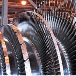
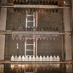
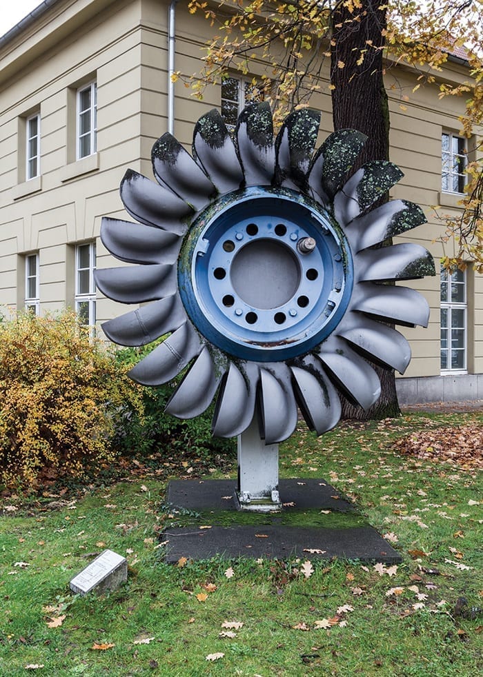
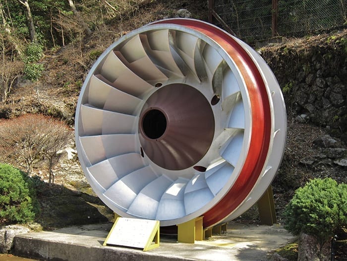
The two basic types of hydraulic turbines are the impulse and reaction. Impulse turbines operate in the highest head (specific energy) ranges and convert the energy in a fluid column into mechanical energy solely by changes in velocity across the runner. The Pelton turbine (Figure 1) is an example of an impulse turbine. Reaction turbines are used in lower and medium heads and convert energy by changes in both velocity and pressure across the runner. Consequently, it is the performance of reaction turbines that is enhanced by draft tubes. Francis (Figure 2) and Kaplan (Figure 3) turbines are examples of reaction turbines.
 |
|
1. The runner shown here is from a Pelton turbine. Source: Creative Commons / Dietmar Rabich |
In hydraulic turbines, if there is any pressure change across the runner, that is sufficient to classify it as a reaction turbine. However, steam and gas turbines are classified as reaction machines only if 50% or greater of the energy conversion is due to pressure changes.
 |
|
2. The runner shown here is from a Francis turbine. Source: Creative Commons / Qurren |
A crossflow or Banki turbine is a hybrid. It is often manufactured with a draft tube. However, even though the runner may operate in sub-atmospheric pressure, there is no pressure change across the runner, and therefore, by definition, it is an impulse machine.
 |
|
3. The runner shown here is from a Kaplan turbine. Source: Creative Commons / Reinraum |
Draft Tube Length and Cross-Sectional Area
Draft tubes are expensive civil features to construct. They require a considerable amount of concrete forming. First, they must start upstream on the underside of the runner in a perfect circular shape, but transition so that at their downstream end they have a rectangular shape. That shape is needed to accommodate rectangular draft tube gates or stoplogs for unwatering purposes.
Further, for large, vertical-shafted turbines, the width at the draft tube exit becomes excessive. Therefore, one or more intermediate lateral piers must be designed to provide structural support in the downstream portion of such draft tube barrels, further increasing forming costs. In addition, the upstream end of the draft tube is armored. That is, a steel lining is embedded to protect the concrete from erosion by cavitation until the maximum velocity of the discharge in the draft tube is less than about 20 feet per second.
The original hydraulic turbines were small machines and the original draft tubes were conical diffusers that pointed straight down. However, as turbines grew larger, such configuration for a draft tube required ever-increasing excavation. Consequently, designs were introduced that put right-angle circular bends in the draft tubes so the exits could discharge horizontally.
However, the overriding design feature of draft tubes has remained consistent, even accommodating the aforementioned round to circular transitions, intermediate lateral piers, and right-angle vertical bends. That is, the cross-sectional flow area perpendicular to the centerline of the draft tube is formed to expand at a constant angular rate so that as the flow velocity decreases the pressure will increase, or stated another way, there will be a pressure recovery. In this manner, any cavitation downstream in the draft tube is avoided and the velocity at the draft tube exit can be designed to match an open channel river velocity and avoid scouring bottom sediments. The U.S. Bureau of Reclamation’s Engineering Monograph No. 20, “Selecting Hydraulic Reaction Turbines,” has both plan and profile designs recommended for draft tubes.
Whirl Component
Reaction turbines convert the energy in a fluid column by using the specific energy in the incoming flow to first impart a whirl or angular momentum to the incoming flow. This is done through the centrifugal action of the spiral or semi-spiral case. The turbine runner is then designed to straighten this flow out by removing the whirl component.
The reaction to removing the whirl component is to impart the equivalent mechanical energy, minus losses, into the turbine-generator shaft. Upon leaving the runner, if all the whirl component is removed, the flow would have a natural tendency to expand at a conical angle of about 12 degrees. To avoid any flow reversal and increased losses, the rate of cross-sectional area increase with draft tube length would need to be less than that angle. This would require a long draft tube with high frictional losses and degrade the efficiency of the turbine.
Consequently, it has been a U.S. practice to leave about 5% of the whirl component in the flow when discharged from the runner. This allows centrifugal action to cause the discharged flow to expand at a conical angle greater than 12 degrees. Thus, draft tubes can be formed of shorter length, cause less frictional loses, and cost less to construct. The design standard in some European countries has been reported to leave 10% of the whirl component in the flow discharged from the runner.
Earlier draft tubes were designed with several internal flow-guidance features. One of these was a Moody cone. This is an inverted, reinforced concrete cone, which extends from the bottom of the draft tube elbow upward toward the center of the bottom of the runner. It was used for vertical-shafted turbines having a large whirl component at the exit of their runner and was intended to reduce the whirling action of water. It was reported to have an efficiency of up to 85%.
Another flow-guidance structure was installed on the first two turbines at the original or first powerhouse at Bonneville Dam on the Columbia river. These were reinforced concrete, horizontal splitter vanes that were also intended to remove any whirl component in the flow being discharged from a runner. An unwatered inspection after the first couple of months of operation found they had all been ripped out flush with the draft tube wall.
Velocity Head
The discharge of water from the exit of the draft tube is a necessary part of the flow process. To be discharged, that water necessarily contains kinetic energy that could not be converted into shaft mechanical energy. Therefore, even if the fluid is inviscid (has no hydraulic losses), a reaction turbine can never truly be 100% efficient. However, any excess kinetic energy that is also discharged is simply wasted and results in a decrease in generation efficiency.
The most common form of Bernoulli’s equation contains the sum of the three forms of fluid energy at any point in the flow process, including issuing from the exit of a draft tube. The equation is:
(P / γ) + (α x V2 / 2 x g) + Z = system constant
where P is the pressure, γ is the specific weight of water, α is the velocity head or Coriolis correction factor, V is the average or mean velocity, g is acceleration of gravity, and Z is the piezometric data elevation.
The small case Greek letter “α” is a coefficient of the velocity head term composed of the square of the average velocity and gravity over a given cross-section. If the average velocity is not uniform or constant over the cross-section, the correction factor is greater than one and the kinetic energy represented by that surplus over one is wasted, decreasing generation efficiency.
Test Codes
For more than seven decades, there have been two test codes for hydraulic turbines. These each have procedures for measuring and calculating the performance of prototype hydraulic turbines. The first is the American Society of Mechanical Engineers Performance Test Code 18 (ASME PTC 18), “Hydraulic Turbines and Pump-Turbines.” The second is the International Electrotechnical Commission (IEC) Publication 41, “Field acceptance tests to determine the hydraulic performance of hydraulic turbines, storage pumps and pump-turbines,” published in Geneva, Switzerland. The ASME code also applies to turbine model tests, while the IEC has a separate publication for turbine model tests.
Originally the two codes had two significant differences. First, the IEC code has sophisticated procedures to calculate test uncertainties or test inaccuracies and apply a band of those values to the test results. The ASME code had no provision for calculating any test uncertainties. Today, both codes have methods of applying test uncertainties to the test results.
The second difference is the location of the downstream energy station for the calculation of the net head acting on the turbine. Specific energy has been adopted by both codes for the term head. Originally, the ASME code specified the downstream energy station was to be the equivalent still water surface one-unit monolith width, downstream from the draft tube exit. However, the IEC code specifies the location as upstream of the draft tube exit so that the sudden expansion losses of the fluid exiting the draft tube can be calculated as though the velocity head correction factor is unity and any wasted excess kinetic energy is not charged against the turbine’s performance.
Experiments conducted at a hydraulic research laboratory found that for both barrels, at two different flow rates, on a large vertical-shafted Kaplan-model turbine located on the Snake River in eastern Washington, the velocity head correction factor was twice that for a uniform velocity profile. The velocity profiles showed the flows for both barrels, at both flow rates, were highest in the barrel centers. In other words, in all cases, twice as much kinetic energy was being wasted by being discharged than was required. Today, both codes specify the prototype downstream energy station is to be inside and upstream from the draft tube exit. In this manner, this inefficiency is not being measured nor charged to the turbine.
Head Augmentation Utilizing a Draft Tube
Over the years, designs have been proposed, developed, and tested for auxiliary water passages to convey unused forebay water directly into draft tubes. The first such method was constructed by Thomas Edison on the Fox River in Appleton, Wisconsin. There, he built the first hydropower plant in the U.S. to power his light bulbs in a friend’s home. This was a low-head plant, reported to be no more than 10 feet.
During floods or high water runoffs, the tailwater would rise and there would not be sufficient specific energy for home lighting purposes. He therefore designed a conveyance in the brickwork of his powerhouse that routed some of the surplus forebay water into a circular expansion at the upstream beginning of the draft tube. This accelerated the total draft tube flow, decreasing the pressure under the runner, and was reported to have restored about 40% of the specific energy lost due to high tailwater.
—Lee H. Sheldon, PE is a hydropower engineer with 50 years of experience. He has published 35 technical papers and a college textbook on hydropower engineering, and has worked on every federal hydroelectric project in the Pacific Northwest, among others. He is presently a senior hydromechanical engineer with KGS Group in Seattle, Washington, and was formerly a professor at the Oregon Institute of Technology, where he taught hydropower engineering and fluid mechanics.