As more intermittent renewable energy resources are added to the power grid, generator connectivity during a grid fault becomes ever more important to mitigate the risk of cascading blackouts. An innovative coupling design may help plants safely achieve fault ride-through requirements.
Most people are aware that renewable energy resources are not a consistent source of power. Wind and photovoltaic systems, in particular, cannot be counted on to respond to an event that triggers demand within the grid. Potential issues can be stabilized in several ways including synchronous condensers, static VAR compensators, and battery storage, but there will continue to be a need for base spinning reserve sources of electrical production to maintain grid power and stability.
Grid instability in the U.S. is not yet a common issue because the U.S. baseload generation model is still centralized and, at a generating level, that provides protection from rolling blackouts or cascading power failures. However, the country’s electrical power generation model is changing with regulatory and economic drivers moving generation more toward decentralization with the constant closure of baseload coal, nuclear, and natural gas power generating stations. As electrical power generation decentralization continues, more and more microgrids develop, and they lack the spinning reserve of energy to cover times of high power demand. Therefore, it becomes more important to maintain the connectivity of all generation sources without interruption.
In Europe, the process of electrical grid decentralization has progressed to the point that generator connectivity to the grid must be maintained during a grid fault for a mandated period of time in order to mitigate the risk of cascading blackouts. This threat to the European power grid has been addressed by Commission Regulation (EU) 2016/631. Even though this regulation substantially targets wind turbines and photovoltaic systems, it still has considerable influence on conventional power plant turbine-generator sets. As a result, turbine-generator systems are required to maintain connection through low-voltage events, short circuit conditions, and breaker reclosures. This grid fault ride-through (FRT) requirement can create serious shaft line mechanical issues for the components of a turbine-generator. These issues occur because of the torques that are developed by the generator during a power system grid fault situation.
Previously, disconnection of the turbine from the generator during a grid or malsynchronization event was allowed to occur via a shaft line torque-limiting device that would release as soon as the set torque was exceeded. The torque limiter release allowed for the separation of the rotating masses of the turbine and generator, protecting them and allowing them to shut down safely. With the resetting of the torque limiter and the restarting of the turbine-generator system, power generation could once more take place.
This release of the torque limiter to protect the shaft line is no longer allowed so that blackouts caused by chain reaction events can be avoided. The function of the torque limiter must now be to maintain the mechanical connection of the turbine to the generator but slip to trim off the torque peaks. These peaks are generated during the mandated time of sustained connection and remain until the breakers are allowed to react. Then, when the breakers re-close while the generator is still operating, the torque limiter will have to provide the same torque limitation. It will slip to accommodate any malsynchronization between the grid and the operating phase angle of the generator.
Present-day turbine-generator sets are designed using three essential philosophies, and the philosophy implemented in each case is reflected in the shaft line coupling design. The system, consisting of the electrical power system, the system fault, electrical machine, shaft line, and controller, has been modeled as a whole, and the transient torque along the shaft line was calculated. The influence of each coupling type within the system has been analyzed, taking into account the current EU regulation and the shaft line coupling design.
Coupling Types in Turbine-Generator Sets
Three different shaft line coupling designs will be considered in relation to the new EU regulation.
The first shaft line coupling design considers a rigid, sustainable version that uses a disc-pack connection coupling where torque is transmitted from the shaft to the hub via a press fit. The connection coupling is selected to withstand infrequently occurring faults, such as gen-set malsynchronization or short circuit events.
The second shaft line design considers a shear-pin coupling design. The shear pins break above the set torque, and torque transmission is no longer possible. Once the shear pins are replaced, torque can again be transmitted and power generated.
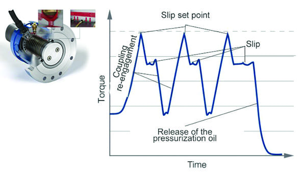
The third shaft line design considers the hydraulically pressurized slipping torque limiter, which also transmits torque from the shaft to the hub with a frictional connection via a press fit (Figure 1). However, the press fit in this case is produced hydraulically using pressurized oil. The selected applied oil pressure makes it possible for the two coupling halves to slip when the set torque is exceeded but not release until the slip angle reaches between 30 degrees and 120 degrees.
 |
|
1. Structure of a hydraulically pressurized slipping torque limiter able to continue transmitting torque in slip mode. Courtesy: Voith Turbo |
System Modeling
The calculation of the transient torques at the shafts of turbine-generator sets requires consideration of the overall system for electrical energy infeed. Essential system levels in this consideration are power grid, disturbances on the grid, transformer, grid connection, and synchronous generator. Each system level is described by a comprehensive system of differential equations. The experts involved intervene to some extent in the power plant structure on a system-specific and location-specific basis.
Depending on the fault event considered, different sensitivity must be accorded to different levels. The shaft line/generator level is deterministic for the torque loads. System-specific data for the respective power plant is absolutely necessary. The same applies to the grid connection conditions and the transformer. A comparable precision in control is necessary in selected studies; often, standard controller structures are sufficient.
Network Faults and Other Malfunctions
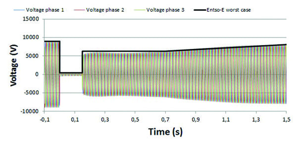
As was previously mentioned, due to the EU regulation, there is now an FRT requirement for conventional power plants in the industrial power range. The requirement indicates that a short circuit in the vicinity of the power plant cannot lead to disconnection of the power plant from the system, referred to as fault ride-through. In the worst case, this results in a voltage curve at the network infeed point corresponding to Figure 2.
 |
|
2. Voltage curve at the network connection point with fault ride-through. Courtesy: Voith Turbo |
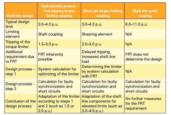
In terms of the load on the mechanical shaft line, this fault case corresponds approximately to a three-phase terminal short circuit with subsequent successful grid-reclosing. The fault ride-through is therefore not a mechanical worst-case situation for the shaft line. For a shaft line design philosophy that operates with a torque limiter, such as a shear-pin coupling, the minimum load-bearing capacity of the pins is defined by this case. The process is reproduced for the different shaft line design types in Table 1.
 |
|
Table 1. Design process taking fault ride-through (FRT) into account with torque limits per-unit (p.u.). Courtesy: Voith Turbo |
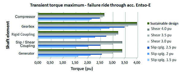
A shaft line that has been designed according to Table 1 subsequently requires testing under substantial faults. These faults include two/three-phase short circuits and, in particular, malsynchronization. This will be shown below in the example of a 9.4-MVA gas turbine set. In Figure 3, it becomes clear for the FRT case that the shearing elements must be strengthened from 3.0 per-unit (p.u.) to a range of 3.5 p.u. to 4.0 p.u. to avoid disengagement of the coupling.
 |
|
3. Maximum torque load depending on the coupling type. Courtesy: Voith Turbo |
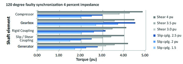
The shaft line modified for this fault case is then stressed further in the event of a malsynchronization (Figure 4) or a two-phase short circuit (Figure 5). Figures 4 and 5 clearly illustrate the challenge presented by the EU regulation. Shaft lines that were previously protected by shearing elements do not comply with the FRT requirement in some circumstances. Any adjustment of the shearing elements in an attempt to comply with FRT requirements will require a very detailed consideration of the complete shaft line relative to the fault cases that may possibly occur.
 |
|
4. Load on the shaft line components in the event of malsynchronization. Courtesy: Voith Turbo |
 |
|
5. Load on the shaft line components in the event of a two-phase terminal short circuit from no load. Courtesy: Voith Turbo |
Outlook for Possible Future Requirements
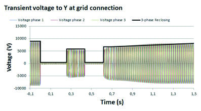
Commission Regulation (EU) 2016/631 should be considered a first measure with regard to changes in the European grid. Over the long-term, an expansion of requirements should be anticipated. Wind and photovoltaic systems entail very low operating costs with decreasing investment costs for new systems. Possible requirements might be, for example, more complicated fault sequences in the grid such as those occurring for a three-phase unsuccessful reclosing (Figure 6).
 |
|
6. Terminal voltage in the event of a three-phase unsuccessful reclosing. Courtesy: Voith Turbo |
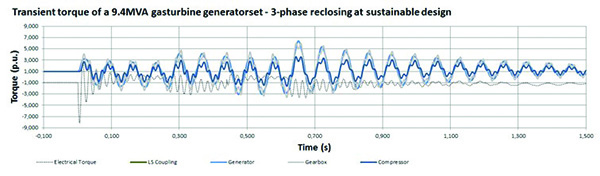
The torque curve over time for this is shown in Figure 7 for a rigid disc-pack coupling design and Figure 8 for a hydraulically pressurized slipping torque-limiter coupling. It becomes clear that a hydraulically pressurized slipping torque limiter allows for the operation of a power plant, even for grid support, without the shaft line having to be designed for the maximum torques that would occur in a rigid disc-pack coupling design.
 |
|
7. Torque curve versus time in the event of an unsuccessful three-phase reclosing with rigid disc pack coupling design. Courtesy: Voith Turbo |
 |
|
8. Torque curve versus time in the event of three-phase reclosing with a hydraulically pressurized slipping torque limiter. Courtesy: Voith Turbo |
Another prospect that can be mentioned relates to the increase of inverter-controlled wind and photovoltaic energy generation and drive units. Their use leads to a clearly increased capacitive component in the European grid with the potential for electrically resonant circuits. The reduction of baseload power generation capacity reduces the available grid short-circuit power at the same time. Electrically resonant circuits can lead to shaft vibrations at sub-synchronous resonances or can excite electrical machines to vibrate on a very local scale causing issues for power users that may be difficult to diagnose.
Summary
Commission Regulation (EU) 2016/631 has considerable influence on the design of conventional turbine-generator lines on an industrial scale. Rigid disc-pack coupling designs already fulfill the requirement inherently. In this case, the shaft lines are already designed to withstand extreme fault cases, such as faulty synchronizations with a 100-degree to 120-degree phase angle. A design such as this will be more expensive to produce because material and component selections will have to meet the criteria to survive the torques developed during a grid-fault event.
Shaft lines with shear-pin couplings must consider the FRT requirement as a key dimensioning criterion. Due to the reinforced shearing elements, not only the coupling but also the shaft line components will have to endure significantly more stress in some cases.
An alternative can be the use of hydraulically pressurized slipping torque-limiter couplings. Modern calculation methods make it possible to design this type of coupling so that the FRT case is satisfied while the shaft line remains protected from extreme fault cases. In addition, these coupling designs are customizable to allow for integration into existing shaft lines and possibly for integration within other shaft line components, such as a gearbox.
Hydraulically pressurized slipping torque-limiter friction couplings are also available with a non-releasing feature for speeds of 3,000 rpm and torques of 500,000 Nm. The amount of slip is still limited between 30 degrees and 120 degrees. This angle no longer leads to triggering of an oil safety valve, which would require replacement and coupling re-pressurization. Instead, the slip angle is monitored externally and must be linked with a decoupling of the turbine set by the generator switch through the generator controls. ■
—Todd Lehman is a product sales manager for Voith Turbo Inc. in York, Pennsylvania, specializing in the company’s SafeSet, SmartSet, and SlipSet torque-limiting couplings. David Bergström is an engineering manager for Voith Turbo Safeset AB in Hudiksvall, Sweden, specializing in new product research and development.