SO3 Control: AEP Pioneers and Refines Trona Injection Process for SO3 Mitigation
Using a selective catalytic reduction (SCR) system to reduce the emissions of nitrogen oxides (NOx) from a coal-fired power plant is rapidly becoming the norm, rather than the exception. But for many plants, adding an SCR system has unintended consequences: greater oxidation of sulfur dioxide (SO2) to sulfur trioxide (SO3), and a rise in stack opacity. This problem is exacerbated on units equipped with flue gas desulfurization (FGD) systems, commonly known as scrubbers, because plants thus equipped typically burn high-sulfur coal.
The plume from a unit equipped with a wet FGD system is readily visible due to the large concentration of water vapor, which condenses readily when it is cooled upon entering the atmosphere. This billowing plume of water vapor is highly visible to the public and can often be misinterpreted as pollution.
SO3 hydrates as it cools when it passes through the air heaters and forms sulfuric acid (H2SO4) vapor. When the H2SO4 vapor passes through the wet FGD it cools further and forms fine sulfuric acid aerosols. In sufficient concentration, the aerosols scatter light and create a visible secondary plume that is typically blue.
The secondary plume’s color and opacity depend on the aerosol concentration, aerosol size, sun angle, gas temperature, and atmospheric conditions. In most cases, a plume is visible when H2SO4 aerosol concentrations in the flue gas exceed 10 to 20 ppm. The higher the plume concentration, the greater the discoloration and the longer the plume remains in the atmosphere. The risk of a plume touchdown is also a real concern.
Although only 0.5% to 1.5% of the SO2 in the flue gas typically is oxidized to SO 3, the additional concentration of sulfuric acid may, under the right operating conditions, produce a highly visible and aesthetically unpropitious "blue plume." This article describes how American Electric Power (AEP) worked through the process of developing and implementing an approach for mitigating SO3 at its General James M. Gavin Plant near Cheshire, Ohio (Figure 1).
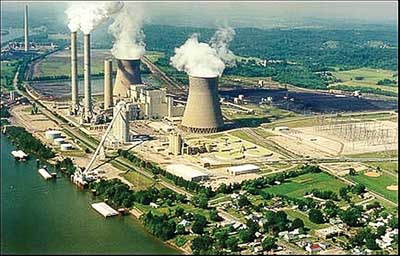
1. At the General Gavin plant, AEP perfected the art of trona injection to reduce SO3 emissions. Courtesy: AEP
SCRs and SO3
Tailoring the catalyst and operation of an SCR to minimize SO3 formation can go a long way toward reducing the visibility of a secondary plume. A typical SCR catalyst consists primarily of tungsten trioxide (WO3), titanium dioxide (TiO2), and vanadium pentoxide (V2O5). Vanadium pentoxide is the active ingredient and the one responsible for the conversion of SO2 to SO3.
The composition of the catalyst should be carefully selected based on plant operating conditions, the concentration of SO2 in the flue gas, the permitted ammonia slip, and the target concentration of ammonium bisulfate. The baseline conversion efficiency of an SCR catalyst can be increased by adding layers. Typically, each layer effects a conversion of 0.2% to 0.8%. Therefore, a three-layer catalyst would convert 0.6% to 2.4% of the SO2 passing through it to SO3.
The effective conversion rate of the catalyst depends on its operating temperature as well. So one could compensate for the use of a catalyst with more layers (better for NOx reduction) and a higher conversion rate by lowering the temperature at the economizer outlet (the inlet of the SCR system).
AEP has found that either approach — choosing a catalyst with a low conversion rate or lowering the operating temperature — can substantially reduce the SO3 concentration in the flue gas downstream of the SCR system. This reduces the cost of other SO3 mitigation equipment required. However, AEP tests have demonstrated that injecting (evaporating) water into the ash-laden flue gas upstream of the SCR to reduce the catalyst temperature resulted in large ash agglomerations. Hence, AEP no longer employs this strategy.
AEP also has found that, depending upon the sorbent employed, significantly reducing SO3 levels can impede particulate collection for units equipped with electrostatic precipitators (ESPs). The cause is the relationship between SO3 and resistivity on cold-side ESPs. Calcium- and magnesium-based sorbents tend to increase resistivity, while sodium- and potassium-based sorbents tend to lower resistivity.
Choosing a Sorbent
Several chemical sorbents are available to control the SO3 emissions of a coal-fired boiler. Some are designed to be added to fuel; others are injected into the furnace; and others work better when injected into the flue gas stream. In all cases, the sorbent reacts with SO3 in the flue gas to form a solid compound that can be removed by the plant’s particulate collection device — an ESP or fabric filter (baghouse).
Sorbents designed to be injected typically use alkaline reagents that contain calcium, magnesium, sodium, or ammonia. Depending on its reagent type, the sorbent can be injected dry or wet, either in aqueous or slurry form. Most dry sorbents are transported by pneumatic conveyors from a storage silo to the flue gas.
Compared with dry injection, injecting solutions and slurries has some disadvantages. For example, wet injection generally requires longer residence times because the reaction typically occurs after evaporation. Another downside of wet injection (depending on where it is done) is that poor atomization may cause ash to agglomerate on internal supports or other boiler island equipment.
Several sorbents have proven successful at reducing SO3 concentrations in flue gas when added downstream of the boiler furnace (either upstream or downstream of the air heater) but upstream of the SCR system, ESP, and scrubber. Among them are magnesium hydroxide, magnesium oxide, calcium hydroxide, sodium bisulfate, ammonia, and sodium sesquicarbonate (trona) — a naturally occurring mineral that is the raw material for soda ash. For maximum SO3 reduction, it is extremely important to match the sorbent to the characteristics of the boiler and its fuel and the configuration of the unit’s emissions control equipment.
AEP has pioneered the use of the sodium-based alkali trona for SO3 mitigation. One reason that trona works is that it avoids the high resistivity problems associated with many alkalis. For the past three years, trona has reduced the SO3 emissions and related impacts (including blue plumes) at the General Gavin plant. Trona injection is now being implemented across AEP’s entire bituminous coal – fired fleet where both SCR and FGD systems are in place.
Where to Inject It
Adding trona (or another sorbent) to the furnace can reduce the concentration of SO3 in flue gas entering the SCR system. But this approach could still result in the release of a visible sulfuric acid plume because the SCR system will still transform SO2 to SO3, especially if its catalyst has a high conversion rate.
Injecting sorbent into the furnace and/or into the ductwork upstream of the SCR system will only remove SO 3 formed in the boiler. With furnace injection, the addition of sufficient excess alkali will continue to remove SO3 generated in the SCR system if the alkali remains present and reactive before and after the system. For example, some magnesium-based sorbents injected into the furnace become unreactive prior to entering the SCR system.
If sorbent is injected upstream of the SCR system, the sorbent must be of the type that will not poison the SCR catalyst. Injecting sorbent in the ductwork after the SCR avoids this constraint and reduces the total SO3 formed both in the boiler and in the SCR system, thereby reducing the level entering the air heater. Lowering the concentration both minimizes the possibility of forming ammonium bisulfate that could plug the air heater and reduces the potential for corrosion caused by operating near the dew point temperature. Reducing the SO3 concentration upstream of the air heater allows the average temperature at its cold end to be reduced, raising the boiler’s efficiency and lowering the generating unit’s heat rate.
Another option for mitigating SO3 formation is injecting an alkali sorbent before or after the ESP. But this approach neither reduces the possibility of ammonium bisulfate deposition in the air heater nor allows lowering the heater’s average cold end temperature. Choosing an injection point upstream of the ESP minimizes the potential for a visible SO3 plume and minimizes acid dew point – caused ESP corrosion as well. But doing so might degrade ESP performance, depending on the sorbent and its effect on ash resistivity. Choosing a point downstream of the ESP creates the unique challenge of collecting particulates in the FGD. Furthermore, there is a potential regulatory issue with injecting a sorbent that reacts to form a solid downstream of the designated particulate collection device.
Testing with Trona
AEP’s SO 3 mitigation system injects dry trona upstream of the ESP. AEP selected trona because it is both highly reactive and compatible with existing ESPs. Furthermore, dry sorbent injection is preferable to liquid injection for several reasons: ease of handling, reduced risk of fouling downstream ductwork or equipment, and improved safety (including lower conveying pressures). The capital cost of a trona injection system is relatively low, but the cost of transporting the trona from its main U.S. source (mines located near Green River, Wyoming) is high for most bituminous coal – fired plants. Operations and maintenance costs are minimal relative to other sorbent technologies. Proper nozzle and lance design is imperative for reliable operation and sorbent utilization.
AEP measures SO3 levels using the controlled condensation method. Measurements at the stack indicated that the SO3 levels attained with trona injection were lower than those produced by injecting both magnesium hydroxide slurry into the furnace and hydrated lime upstream of the ESP.
To readers considering trona, be aware that AEP wrestled with two fundamental problems before finding solutions that are now being implemented fleetwide: material handling and deposition.
The material-handling issues included fluidity (flow interruptions), rat-holing, agglomeration, unloading problems, and inadvertent material degradation. For example, vendor data describe trona as "not hydroscopic." Though this is technically true, unlike quicklime (which can slake in the air), trona has a chemical affinity for water that AEP field and laboratory tests confirmed.
Indeed, one of the root causes of the material-handing problems was moisture absorption. As a result, AEP now includes moisture content and temperature controls in its systems for handling trona deliveries (Figure 2). In general, AEP is looking for trona delivered to a plant to have less than 0.03% free moisture, a maximum particle diameter of 25 to 35 microns, and the highest possible purity and bicarbonate ratio (Figure 3).

2. Trona is delivered in sealed rail cars to keep it dry. Courtesy: AEP
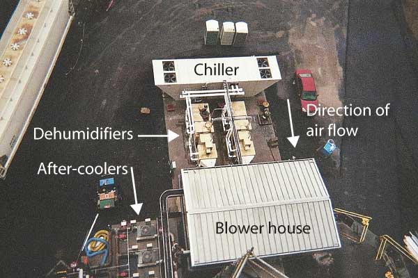
3. Rail unloading of trona at the Gavin plant’s distribution center. Note the dehumidifiers and chiller, which keep the sorbent dry and cool after unloading. Courtesy: AEP
Duct deposition, which was not observed during the testing phase, was first observed when Gavin Unit 2 had to be shut down for unrelated maintenance after several months of trona injection. AEP did not implement measures to address the deposition at that time. After several more weeks of operation, a second, unrelated forced outage provided another unexpected inspection opportunity. This time, inspectors observed that the flow distribution screen upstream of the ESP was severely plugged on one side, resulting in severe damage to the first ESP field. The source of the damage was diagnosed as plate failures from self-excited vibrations generated by localized high flue gas velocities caused by the plugged screen.
Hard-Earned Experience
AEP immediately began an investigation. Duct inspections showed that the duct’s "hot" side had deposition, while its "cold" side did not. Deposition samples were removed for analysis. X-ray diffraction was attempted, but the samples were amorphous and the crystalline structure could not be determined.
The sorbent supplier had never experienced this type of deposition before because trona had traditionally been used to remove SO2, not SO 3. The supplier suggested that the deposition might be due to ammonium bisulfate or the reaction of ammonia with trona. However, AEP conducted testing without ammonia injection and the deposition rate was unchanged, eliminating ammonia as a suspected cause.
Microscopy indicated that almost all of the deposit was flyash. Its agglomeration seemed to be caused by a minute amount of another element. Plant personnel noted that the deposition appeared to be temperature-related. Deposition coupons were fabricated and installed in the duct to test the theory, and deposition data were taken almost daily. The data were consistent with observations suggesting that the deposition was temperature-related.
The pH readings, visual observations, deposition data, and elemental analysis all pointed to liquid sodium bisulfate formation as the likely cause of the ash agglomeration and deposition. Kinetic modeling determined the precise (theoretical) liquification temperature of sodium bisulfate and this supplemented field data to establish a maximum peak duct temperature.
Design changes were made to the trona injection system to test the theory. Quench air was introduced on one of three ducts on one unit to keep the peak flue gas temperature below the critical temperature determined by the field data supplied from monitoring the rate of deposition on the deposition coupons. On another duct without quench air, a rapper was installed on one of the ESP flow distribution screens.
Computational fluid dynamics modeling confirmed that some turning vanes could be removed without significantly affecting the differential pressures at duct turns. Removal of unnecessary turning vanes was worth trying because that would reduce the surface area on which deposition could form. The modification was completed on all three ducts on both of Gavin’s two units.
After one ozone season, results were uniformly successful (Figure 4). The duct with the quench air experienced almost no deposition and required no on-line cleaning. Ducts without quench air had measurable deposits and required some on-line cleaning to avoid plugging of turning vanes. The ESP screen was kept clean by the mechanical rapper. These modifications were subsequently installed on the other ducts and ESP screens of both Gavin units and have operated without problems for two ozone seasons.
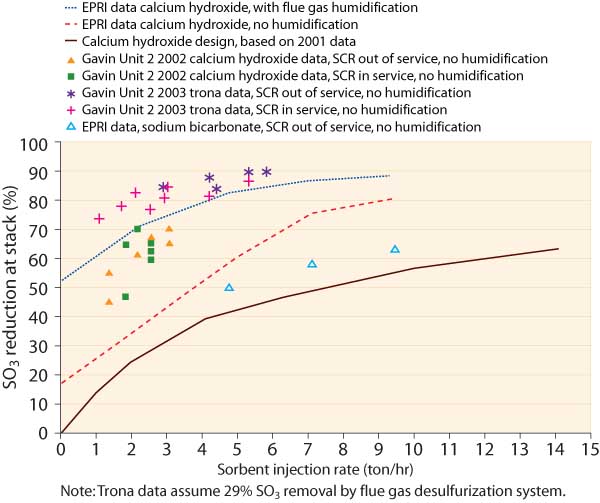
4. AEP’s Gavain Unit 2 SO3-mitigation results compared with EPRI data and original design basis. Source: AEP
Open for Business
As mentioned, AEP is implementing trona injection across its entire bituminous coal – fired fleet (Figure 5). The company has filed a patent application for its unique process for using trona to mitigate SO3 (Figure 6). AEP also is seeking nonexclusive licensees of the process in the hope of disseminating this technology throughout the industry. Currently, Babcock & Wilcox is the only licensed vendor of this technology.
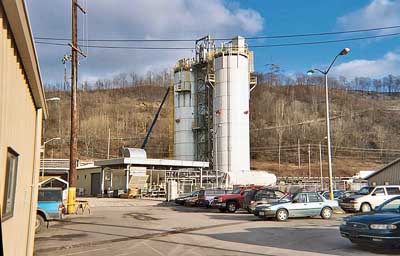
5. New trona silos were reently commissioned at AEP’s 2 x 800-MW Mitchell Plant near Moundsville, W.Va. Courtesy: AEP
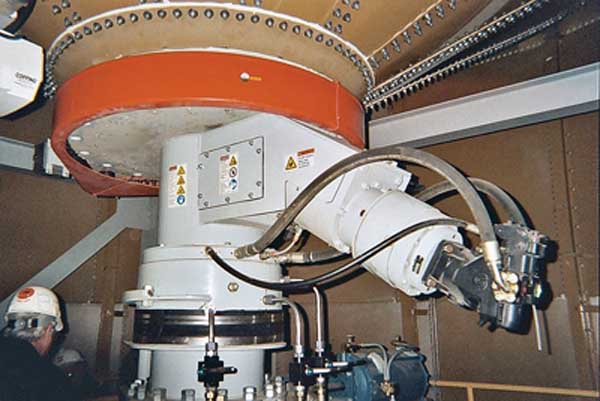
6. The reclaim unit at the bottom of the Mitchell Plant’s storage silo is designed to move trona, even if it is wet. Courtesy: AEP