SCR Reheat Burners Keep NOx in Spec at Low Loads
Optimal NOx removal by a selective catalytic reduction (SCR) system requires the inlet gas temperature to remain within a prescribed range. How does a baseload unit meet NOx permit limits when it’s cycled and SCR inlet gas temperatures dip?
Selective catalytic reduction (SCR) systems installed in steam generators for NOx reduction are ordinarily designed for full boiler load conditions, when SCR inlet temperatures normally exceed unit-specific temperatures in order for the catalyst to function efficiently. Under full-load conditions, SCR units operate at optimum levels of NOx reduction, often exceeding 90%, with minimal ammonia slip, although the optimum temperature range heavily depends on the type of catalyst used and the flue gas constituents.
The unit operating profile when an SCR was added often bears little resemblance to its operating profile today, now that low-load operation has become increasingly common. Low natural gas prices have spurred construction of high-efficiency combined cycle plants that now compete with coal-fired generation in many regions of the U.S. for the top spot in the dispatch order. Also, some units are disadvantaged in the dispatch order because large amounts of renewable energy are available, principally wind and particularly at night, which tends to push coal-fired units into cycling or load-balancing service.
A coal-fired unit originally built as a baseload unit but now forced into cycling service will experience lower SCR inlet gas temperatures, which in turn will reduce the SCR catalyst’s ability to efficiently remove NOx. In addition, reduced gas temperatures can reduce SCR catalyst activity due to pore blockage on the catalyst surface from the condensation of ammonium bisulfate (ABS) and ammonium sulfate (AS).
At full load, the SCR inlet temperature exceeds the salt dew point; therefore, salt condensation is avoided. At below design gas temperatures, ammonium salts are formed when ammonia is injected into the flue gas to react with NOx due to undesirable side reactions with SO3 and H2SO4. As these salts deposit on the SCR catalyst, there is a resulting loss of catalyst de-NOx capability, as access for the SCR reactants (NOx, NH3v and O2) is inhibited.
The natural consequence of reduced SCR inlet temperatures is to experience catalyst deactivation and/or increased ammonia slip. Increased ammonia slip can also cause plugging or corrode downstream components, and ammonia absorption by fly ash may affect disposal or reuse of the fly ash.
SCR Performance Problem Solving
Coal-fired units experiencing one or more SCR problems caused by cycling or load-following service just described have three potential solutions to their problem.
One common option is to install gas-side economizer bypass ductwork to divert a portion of the hot flue gas that would normally enter the economizer and send it directly to the inlet of the SCR. This option has three important issues that must be addressed.
First, an economizer bypass can be an expensive option due to the high capital and installation costs for the structural steel, bypass ducts, diverting dampers, actuators, and expansion joints. The existing flue gas ductwork often makes locating new ductwork for the economizer bypass difficult. Second, some plants have required pressure part modifications associated with “split” economizer designs. Third, less energy is transferred to the boiler feedwater with an economizer bypass. The consequence is a small reduction in boiler efficiency and, therefore, a corresponding increase in fuel consumption in order to maintain required steam production.
Another option that has found favor is to make a fuel switch to low-sulfur coal. A coal that produces a lower concentration of SO3 at the SCR inlet will reduce the formation of ABS and AS. This option can be very expensive, as the delivered cost for low-sulfur coal is often higher than for medium- to high-sulfur coal. Many other unit and plant equipment upgrades are required to efficiently and safely burn low-sulfur coal. If refueling is a viable option, then begin your research by contacting the PRB Coal Users’ Group (www.prbcoals.com).
The third and lowest capital cost option for solving low SCR inlet gas temperature problems is to install one or more SCR reheat burners in the ductwork upstream of the SCR inlet (Figure 1). Typically, one or more register burners can be strategically mounted directly on the outside of the existing SCR ductwork, which is particularly effective in high-ash environments.
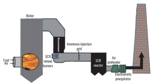 |
| 1. Heating flue gas. Register burners can be added to existing ductwork upstream of the ammonia injection grid to heat the flue gas in order to obtain optimum performance of the selective catalytic reduction (SCR) system under all operating conditions. Source: Forney Corp. |
Register burners inject high-velocity, high-temperature air directly into the flue gas stream across the width of the duct. This results in even mixing and a uniform temperature distribution to the SCR ammonia injection grid that is critical for efficient SCR operation. Also, the register burner design eliminates the problems of slagging, ash buildup, and burner fouling. The external burners also minimize added system pressure drop.
A typical register burner system consists of a gas or oil burner, igniter, flame detector, combustion air blower, combustion chamber, and a burner management system (Figure 2). Design and layout of the burner system is determined using computational fluid dynamics modeling, ensuring optimal heat distribution across the ammonia injection grid.
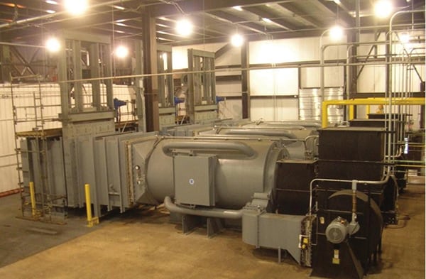 |
| 2. Retrofit register burner. A fully assembled register burner system includes a combustion chamber, combustion air blower, and burner management system. Courtesy: Forney Corp. |
Noteworthy Case Study
Northern Indiana Public Service Co. (NIPSCO), one of the seven energy distribution companies of NiSource Inc., produces and supplies electricity to the northern third of Indiana. NIPSCO is also the state’s largest natural gas distribution company. NIPSCO’s Bailly Generating Station (BGS) is located in Chesterton, on the shore of Lake Michigan, in northwest Indiana (Figure 3). The plant consists of two supercritical coal-fired units.
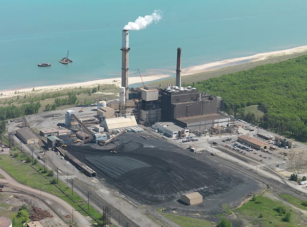 |
| 3. Indiana plant on Lake Michigan. NIPSCO’s Bailly Generating Station consists of two coal-fired supercritical units built in the 1960s that share a common stack. Courtesy: NIPSCO |
Unit 7, which entered service in 1962, uses a Babcock & Wilcox (B&W) cyclone boiler that produces 160 MW. Unit 8, also using a B&W cyclone boiler, has a net full-load output of 320 MW and was installed in 1968. The plant burns bituminous coal containing about 3% sulfur. Both units are equipped with SCR for NOx control, electrostatic precipitators for particulate matter (PM) control, and SBS Injection for SO3 control. The two units share a common wet limestone flue gas desulfurization system and stack.
The plant has been operating, since January 2011, under the terms of a legal settlement between NIPSCO and the U.S. Environmental Protection Agency regarding compliance with the Clean Air Act. The consent decree specifies the maximum 30-day rolling average emission rates for NOx, SO2, and PM emissions for both units combined. Emissions data are collected by the plant’s continuous emissions monitoring system mounted on the combined stack, and a new 30-day rolling average is calculated each calendar day. The average emission rates that occur during the daily averaging period specifically include startup, shutdown, and malfunctions that may occur each day. The consent decree does allow for specific malfunctions that qualify as a force majeure event that aren’t factored into the rolling average emission rate.
Both units are operated based on system demand and are regularly cycled. During reduced load conditions, the flue gas temperature often drops below the 645F minimum temperature setpoint for the operation of the Unit 8 ammonia injection system for the SCR, as the June through October 2010 operating data illustrates (Figure 4). This system limitation means that when the plant is dispatched to lower loads that reduce the flue gas temperature below 645F, the ammonia injection system does not start, SCR efficiency remains low, and the plant could fail to meet the 30-day rolling average NOx limit (0.18 lb/MMBtu) specified in the consent decree.
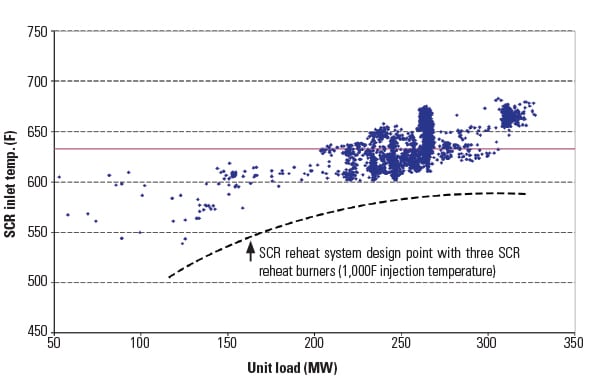 |
| 4. Adding burners. NIPSCO’s Bailly Generating Station added three natural gas–fired 40 MMBtu/hr register burners to Unit 8 (whose data are shown in the figure) and one to Unit 7 in 2011. Each burner has a maximum firing temperature of 1,000F. Burners are engaged when the flue gas temperature entering the SCR drops below 633F (marked by the red line) and the gas is reheated to approximately 633F. The dotted line illustrates the maximum capability of the Unit 8 SCR reheat system. Data are for Unit 8 operations during October 2010. Source: NIPSCO |
BGS determined that adding four Forney natural gas–fired register burners (three on Unit 8 and one on Unit 7) minimizes the risk of the plant failing to meet NOx emissions limits during low-load operation and thereby avoids expensive penalties associated with noncompliance. The four register burners were installed in 2011.
The register burners were delivered to BGS three months after drawing approval. The three Unit 8 burners were lifted into place in June 2011 and placed onto a structural foundation adjacent to the SCR inlet ductwork. Each SCR burner assembly weighs approximately 17,600 pounds (Figures 5 and 6).
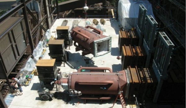 |
| 5. Assembling burners. The three burner systems are preassembled prior to installation on Unit 8. Courtesy: NIPSCO |
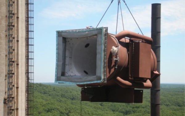 |
| 6. Burner lift. A register burner is lifted into place on Unit 8. Courtesy: NIPSCO |
The SCR register reheat burners are monitored and modulated by two separate control systems: the burner management system (BMS) and the combustion control system (CCS). An Invensys I/A Series distributed control system (DCS) using a dedicated pair of fault-tolerant CP270 controller modules manages each of the three control systems. BGS also uses the Invensys DCS platform in other areas of plant operation.
During operation, the heat load at the outlet of the economizer is calculated by the CCS by multiplying the difference between the economizer average outlet temperature and SCR inlet temperature with the specific heat of the flue gas and the flue gas mass flow rate. This value is “trimmed” by the SCR inlet temperature trim controller, and the final calculated value is used by the CCS as the heat that must be added to the economizer outlet gas (heat) to maintain the necessary SCR inlet temperature. The number of burners required (Unit 8 only) is determined by dividing the heat by the maximum thermal energy available from a single burner. The BMS determines when burners are started and stopped once the system is in service. Multiple burners are operated in parallel in order to maintain a uniform exit gas temperature across the duct at the ammonia injection grid.
Compliance Risks Avoided
The 320-MW BGS Unit 8 has experienced no loss of ammonia injection at reduced load since the SCR reheat burners were installed in June 2011. The burners have worked flawlessly in maintaining the minimum ammonia injection temperature above 635F under all operating conditions. BGS also reports that the 635F permissive temperature for ammonia injection can be maintained down to 180 MW, which gives the utility additional flexibility in plant dispatch.
An added benefit is the ability to use the SCR reheat burners during unit startup time from cold start to full load. Depending on the specific boiler conditions during ramp-up, one, two, or three reheat burners are engaged. This can reduce the startup time by 2 to 6 hours as the ammonia injection permissive temperature is achieved faster. This has a positive influence in the compliance emission rate calculations. ■
— Robert Parent (robert.parent @forneycorp.com) is sales manager for Forney Corp. Bruce Rivera (brivera @nisource.com) was NIPSCO’s project manager for the installations.