Repowering South Mississippi Electric Power Association’s J.T. Dudley, Sr. Generation Complex
Repowering two units at the J.T. Dudley, Sr. Generation Complex added 180 MW of high-efficiency capacity to South Mississippi Electric’s portfolio. Now the cooperative can self-produce more than 50% of its electricity needs.
The J.T. Dudley, Sr. Generation Complex, owned and operated by South Mississippi Electric (SME), is located in Jones County, Miss. Originally installed in 1968 at what was then called the Moselle Generating Station were Units 1, 2, and 3, nearly identical 60-MW conventional steam plants. Units 4 and 5, General Electric (GE) 7EA simple cycle combustion turbines, were added in 1997 and 2005, respectively.
Today, the complex consists of five units capable of generating more than 500 MW. The additional capacity will pay long-term dividends to SME’s customers in the form of increased system reliability and more control over its production costs. The cooperative forecasts that as of 2013 it can self-generate 51% of its power needs; it purchases bulk power for the remainder.
The repowering project converted Units 1 and 2 into two, independent 1 x 1 combined cycle units. Both original gas-fired boilers were retired in place and the steam source for each unit was replaced with a new GE 7EA combustion turbine (CT) and a Vogt Power International (VPI) heat recovery steam generator (HRSG). The new power block is located approximately 400 feet from the existing powerhouse, with piping and cable tray routed along a three-level pipe rack between the HRSGs and powerhouse (Figure 1).
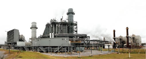 |
| 1. Plant overview. SME’s J.T. Dudley, Sr. Generation Complex repowered two of its three conventional steam plants built in the late 1960s (far right) using two GE Frame 7EA combustion turbines (left) and two heat recovery steam generators (HRSGs, center). The steam produced by the HRSGs is moved across a pipe bridge to the existing steam turbines. Courtesy: Burns & McDonnell |
Construction began in August 2010. The commercial operation date (COD) for Unit 2 and Unit 1 combustion turbines in simple cycle operation was November and December 2011, respectively. The COD dates for Unit 2 and Unit 1 in combined cycle operation were May and November 2012, respectively.
Burns & McDonnell provided consulting, detailed design, procurement, construction management, and startup services. SME designed, procured, and installed the CT generator step-up transformer and interconnection power line, as well as the existing plant switchyard expansion.
A multi-phase and multi-contract approach was used on the remainder of the project. Beginning in August 2010, James Construction Group kicked off construction with site civil work and foundations, plus electrical and mechanical underground construction. Next, PCL Constructors followed in December 2010 with the combustion turbine and simple cycle portion of the construction project. The Saxon Group handled the final two major construction contracts: electrical and HRSG erection plus the combined cycle balance of plant, beginning work in January 2011 (Figure 2).
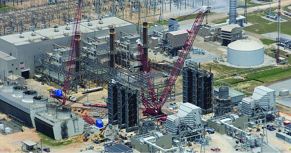 |
| 2. Refurbish instead of rebuild. The existing three conventional units are shown in the background (outdoor boilers with a single steam turbine building located behind the boilers) with the two existing 7EA simple cycle combustion turbines (CTs) to the right of the existing units. The new 7EA CTs are visible in the foreground. Between the new CTs and the three existing boilers are the two HRSGs being assembled. Each 7EA-HRSG combination supplies steam to a single, existing steam turbine. The HRSGs are Vogt Power International’s Enhanced Constructability Smart design. The design incorporates pressure parts, pressure part support steel, interconnecting piping, casing, and structural steel into only six shop-fabricated module boxes per HRSG, significantly reducing erection labor expense. The photo was taken during constructionin October 2011. Courtesy: Burns & McDonnell |
Design Characteristics
The engineering and design of the repowering project was performed with two goals in mind: increased operational flexibility and reuse of existing equipment, where feasible, to minimize project cost. Reused equipment included the steam turbine, boiler feed pumps, condensate pumps, condenser, cooling towers, deaerator, plant air system, and flash evaporator. Details about the major components and equipment used on the repowering project follow.
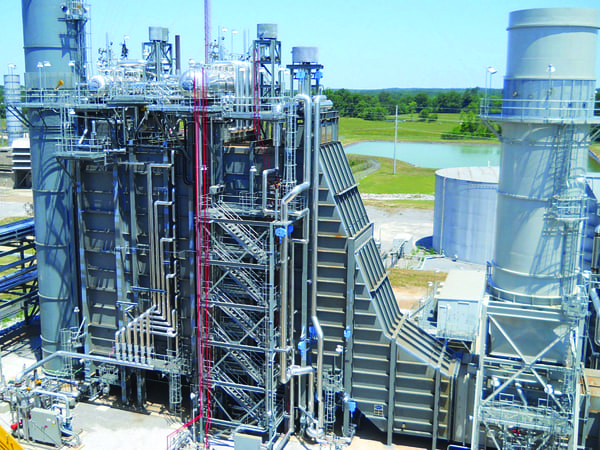
Combustion Turbines. The two new natural gas–fired GE 7EA CTs are equipped with dry low-NOx technology (DLN1) and each is rated at ~85 MW. Each CT is also equipped with evaporative cooling technology, which increases summer capacity by ~8 MW. At full load, the combustion turbines will provide a flow of 2,225,000 pounds per hour of exhaust gas at 1,022F to each HRSG (Figure 3).
 |
| 3. New power block. One of the two new gas-fired GE 7EA combustion turbines is shown. The ductwork located on top of the CT is the air inlet system that includes an evaporative cooler. The upper left shows the CT bypass stack during erection with a small portion of the new HRSG shown at the upper left edge of the photograph. A bypass damper is located at the base of the bypass stack, which may be closed to direct CT exhaust gas through the bypass stack or opened to allow the gas to continue to the HRSG. Courtesy: Burns & McDonnell |
Heat Recovery Steam Generators. The VPI HRSGs are two-pressure, non-reheat, natural circulation drum type with horizontal gas flow and duct firing. A two-pressure non-reheat HRSG economically maximizes the combined cycle efficiency of the repowered 1960s technology non-reheat steam turbines. Given the steam turbine flow limits and the cost of a new steam turbine, an HRSG with more than two pressure levels was not cost justified.
Coen Co. Inc. supplied the duct burner system that is located after the finishing high-pressure (HP) superheater section within the casing of the HRSG. The system includes pressure-reducing and flow measurement stations, burner runners mounted horizontally across the HRSG duct, a burner management system, and a cooling air blower skid for flame scanners. Duct-firing the HRSG can increase the HP superheater outlet flow rate up to 60%, thus adding the ability to quickly respond to load fluctuations.
In addition to the CT’s DLN1 system, a selective catalytic reduction (SCR) system is located downstream of the HP evaporator to further reduce NOx emissions. A 19% aqueous ammonia reducing agent is injected onto the catalyst as part of the NOx reduction process. In sum, the system is capable of reducing NOx emissions by 98%. A space allocation was provided upstream of the SCR to accommodate a future CO catalyst.
To maximize HRSG heat recovery, a condensate preheater is provided just upstream of the HRSG exhaust stack, which heats condensate to near saturation temperature prior to entering the existing deaerator. A recirculation system is used to maintain a minimum condensate inlet temperature to the HRSG to prevent external condensation and corrosion on preheater tubes. The system has two 100% recirculation pumps that take hot condensate exiting the preheater and mixes it with cold condensate entering to maintain a minimum inlet temperature of 140F (Figure 4).
 |
| 4. Maximize steam production. The HRSG produces ~300,000 lb/hr of high-pressure (HP) steam at 950F/780 psig and ~55,000 lb/hr of low-pressure (LP) steam at 520F/74 psig when the CT is operating at baseload at average ambient conditions, with no duct firing. The steam production can be peaked by duct firing the HRSG. Under maximum duct-firing conditions, the HP and LP superheater outlet flow rates are approximately 490,000 lb/hr at 950F/1,280 psig and 45,000 lb/hr at 590F/100 psig, respectively. The maximum heat input to each duct burner is 240 MMBtu/hr. Courtesy: Burns & McDonnell |
Stack Bypass System. The stack bypass system adds operating flexibility by allowing each CT to operate independently of the HRSG, such as during a steam turbine outage or trip. However, the number of hours each year the bypass may be used is limited by the plant’s operating permit. The combustion gas bypass system also allowed SME to generate power in simple cycle mode during construction of the combined cycle portion of the project. For additional safety, a blanking plate was installed on the diverter outlet to the HRSG, allowing construction to progress while operating the combustion turbines.
WhalcoMetroflex supplied the gas flow diverter damper, Merrill Iron & Steel supplied the bypass stack, and Higgot Kane, a division of ATCO Noise Management, supplied the bypass stack silencer. The gas flow diverter uses a toggle-driven single blade within an internally insulated cube. The single blade directs combustion turbine exhaust flow by isolating either the bypass stack inlet or HRSG inlet. The blade offers 99.97% sealing efficiency by mating with a double seal boundary that uses pressurized seal air to eliminate exhaust gas leakage. The blade completes a cycle in only 90 seconds and can close to bypass position in 60 seconds in an emergency. The gas flow diverter damper allows online switching from combined cycle to simple cycle mode but does not allow switching from simple cycle to combined cycle.
Steam Turbine Refurbishment. GE originally furnished the Unit 1 and 2 steam turbines in 1968. Each is a 17-stage straight condensing unit rated at 60 MW. Each was designed to pass 503,000 lb/hr of steam at inlet conditions of 1,250 psig/950F and exhaust 354,000 lb/hr to the steam condenser vacuum of 2.5 inches HgA. The steam turbine has five uncontrolled extraction openings that were used for feedwater heating.
GE performed a study to determine the most efficient and cost-effective way to repower the steam turbines using steam produced by an HRSG instead of by a conventional boiler. Numerous options were evaluated, ranging from minimum turbine modification required for safe operation to completely replacing the steam turbine’s steam path to optimize efficiency and improve reliability.
SME determined that the best economic choice was to replace the steam path with modern components and enjoy the long-term economic benefits of a more efficient steam turbine. All the steam turbine upgrades—design, manufacturing, and assembly of the upgraded steam path—were performed by GE (Figure 5).
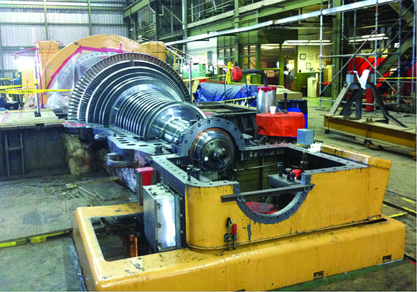 |
| 5. Modernized steam turbine. As part of the repowering project, the two existing steam turbines were retrofitted with modern steam path components. The replaced parts include a new 17-stage rotor forging with new buckets, nozzles, shaft packing, bucket seals, and control valve camshaft assembly. The mechanical components found to be acceptable for reuse were the turbine casing, thrust bearings, and shaft end coupling. Courtesy: Burns & McDonnell |
The turbine redesign required modification of all five turbine extraction ports. Each modification followed ASME TDP-1, Recommended Practices for the Prevention of Water Damage to Steam Turbines (see “Preventing Turbine Water Damage: TDP-1 Updated,” August 2009, in the POWER archives at powermag.com). HP extraction No. 1 and LP extractions No. 4 and No. 5 were not required in the repowered arrangement. Instead, each was cut, capped, and turned into a drain pot with redundant level switches and a small-bore drain line routed to the condenser. A motor-operated valve was located in each drain line that opens when a defined liquid level is sensed by the level switch. HP extraction No. 2 was converted to a bleed line to the existing flash evaporator, which is used for makeup to the cycle rather than a demineralizer. Flow in the bleed line varies between 0 and 19,000 lb/hr, depending on makeup demand. The bleed line low point drains were also modified with drip pots. Extraction No. 3 was converted to an LP steam admission point.
GE’s turbine redesign included upgrades to steam inlet valves and overspeed trip protection. Butterfly style LP admission stop and control valves were located near the turbine. The HP stop and control valve actuators were replaced with direct-acting, high-pressure actuators. A new, high-pressure hydraulic power unit (HPU) replaced the existing low-pressure HPU and supplies hydraulic oil to the LP and HP stop and control valves. A new trip manifold assembly (TMA) was incorporated for overspeed trip protection. The TMA is a hydraulic circuit that protects the steam turbine by closing the admission stop valves in emergencies. It replaced the existing mechanical overspeed trip device.
At fired baseload operating conditions, the modernized steam turbines produce 66 MW, a 10% increase in output. Each can pass 490,000 lb/hr of HP steam at 950F/1,160 psig and 28,000 lb/hr of LP steam at 590F/100 psig. The exhaust flow was designed between 518,000 and 499,000 lb/hr at 3 inches HgA, depending on the extraction flow to flash evaporator. HP steam inlet flow decreased by 3%; however, exhaust flow increased approximately 30% when the extraction ports were secured and with the addition of the LP steam admission.
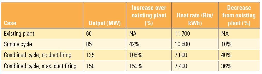 |
| Plant performance test results. Source: SME |
Steam Turbine Bypass. The plant is equipped with a 100% HP and LP steam turbine bypass system, which directs steam to the condenser rather than venting to atmosphere during startup and trip conditions. The bypass system required modification of the existing condenser as well as the addition of engineered HP and LP steam bypass valves. During startup conditions, after condenser vacuum is established, the bypass valves control steam flow to the turbine based on turbine shell temperature and bypass the remaining steam flow to the condenser. During trip conditions, the bypass valves direct 100% steam flow to the condenser and prevent a steam system overpressure event that can result in lifting of safety valves.
Control Components Inc. (CCI) provided the bypass valves chosen for the steam bypass system. The HP bypass valve is configured as a 10-inch inlet to 18-inch outlet pressure-reducing valve with exterior steam ring attemperator. The valve is designed to reduce approximately 310,000 lb/hr of steam at 931F/750 psig to steam at 417F/175 psig. The LP bypass valve consists of a 10-inch inlet to 10-inch outlet pressure-reducing valve with integral steam attemperating nozzle. The valve is designed to reduce approximately 64,000 lb/hr of steam at 521F/91 psig to steam at 358F/70 psig. Both the LP and HP bypass valves are located approximately 100 feet from their respective condenser inlets.
De Laval Turbine Inc. furnished the condensers that were originally installed in 1968. They are single-shell, two-pass, divided condensers with an LP feedwater heater located in the condenser neck. Thermal Engineering International performed a mechanical design evaluation and concluded that each of the condensers could be retrofitted with a 100% HP and LP steam bypass valve. An 18-inch HP bypass line with 336 holes (½-inch) and a 10-inch LP bypass line with 264 holes (3/8-inch) were designed to fit in the condenser transition and pass 400,000 lb/hr and 70,000 lb/hr, respectively. A 3-inch spray water curtain line was designed to fit in the condenser above the bypass lines to keep temperatures below 200F to protect the condenser expansion joint and steam turbine.
Structural modifications were made to the condenser transition to facilitate additional loading from the bypass lines. Tube stakes and steam impingement protection were added to the tube bundles for reducing tube vibration and for protection from increased steam velocity from the bypass lines.
Performance Goals Met
Performance testing for the combustion turbines in simple cycle operation was completed in November 2011 and combined cycle performance testing was completed in April and October 2012, respectively. The table shows the results of that testing for different operating cases. The performance goals for the project were met: Plant output increased 150% and the heat rate decreased 39%.
The additional operational flexibility provided by the combustion gas bypass system and the steam turbine bypass system now permits stable operation from 55 MW to 150 MW for each of the two repowered units. In addition, the capacity addition has increased the SME’s overall system efficiency so that its members will enjoy reasonably price power for decades to come.
— Joseph W. Mashek ([email protected]) and Benjamin L. Frerichs ([email protected]) are business development managers for Burns & McDonnell. Chris K. Rhodes ([email protected]) is generation projects manager for South Mississippi Electric Power Association.