Pulverized Coal Pipe Testing and Balancing
The first step in optimizing combustion system performance is balancing the air and fuel flowing through each of the plant’s coal pipes—the pipes that convey the air/fuel mix from the pulverizers to the individual burners in the furnace wall. Also necessary is information on the properties of the coal traveling through the pipes, such as fineness data. Together, the data provide a window into coal pipe performance that is an important precursor to optimizing furnace combustion efficiency. Fuel fineness and distribution are prerequisites to achieving the best furnace effectiveness for low-NOx burner performance, slagging, and steam cycle performance.
When fuel and air are flowing through the pipes to each burner equally, and the quality of the fuel is within specific guidelines, then the system is balanced. It’s our experience that some plants pay attention to balancing air and fuel flows across coal pipes, but few actually sample the coal flowing to the burners from all of the coal pipes. Those plants are missing an opportunity to improve the combustion efficiency of their furnaces. These measurements play a crucial role in adjusting fuel and air flows to balance the flow, fuel fineness, and air/fuel ratio across all of the plant’s coal pipes (see sidebar).
Air and Fuel Tests
Characterizing air and fuel flow requires carefully collecting a number of measurements, including pipe static pressure, pipe temperature, dirty air velocities, fuel flows from each individual coal pipe, individual pipe velocities, total pulverizer fuel flow, and total airflow entering the mills (primary airflow, including air in-leakage and seal air). The following discussion focuses on the importance of an accurate and standardized coal pipe sampling methodology.
As part of the usual process of ensuring a balanced coal flow system, actual coal samples must be taken from each coal pipe. There are three general approaches to collecting a coal sample, as illustrated in Figure 1. Isokinetic sampling (left) collects particles flowing into the sampler at the same velocity as the coal flowing through the pipe and best represents actual operating conditions. Super isokinetic sampling (center) has particles pulled into the sampler at a higher rate than the velocity in the pipe. Sub isokinetic sampling (right) has particles pushed away from the sampler tip due to its obstruction, and those particles that enter the sample pipe are flowing at a velocity slower than the pipe flow.
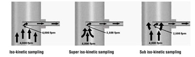
1. Collecting coal samples using an isokinetic probe provides the best data describing actual operating conditions inside the coal pipe. Source: Storm Technologies Inc.
The isokinetic coal sampling method, although more difficult, is the best option for determining the true mill coal fineness produced and to calculate pulverizer performance. We perform isokinetic coal sampling after the dirty air velocity probe traverses are completed. This is done to match the sampling extraction velocity with the actual coal particle velocities in the coal pipes.
Our approach to measuring dirty airflow in coal pipes (fuel and air) is to assemble a dirty airflow test kit (Figure 2) and an isokinetic coal sampling test kit to collect representative fuel samples for coal fineness analysis (Figure 3). Unlike other sampling methods, these two tests together allow the test engineer to determine important performance data, such as:
- Relative pipe-to-pipe fuel balance
- Individual fuel line air/fuel ratios
- Pulverizer air/fuel ratio
- Individual fuel line velocity and airflow
- Pipe-to-pipe airflow balance
- Fuel line temperature and static pressure
- Total fuel flow at different feeder speeds

2. Dirty air test equipment. Source: Storm Technologies Inc.
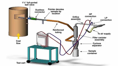
3. Isokinetic coal sampling test equipment. Source: Storm Technologies Inc.
Isokinetic Testing
Our isokinetic coal sampling test begins with marking off the fuel lines to be sampled for an equal area traverse. With the proper number of test ports installed and a favorable coal pipe sampling location, any roping (an unmixed streamline) of coal past the sampling location can be measured and recorded. Figure 4 illustrates a detailed view of a 48-point traverse along the axis of the coal pipe measured (if 10 diameters upstream from the bend or horizontal run aren’t available).
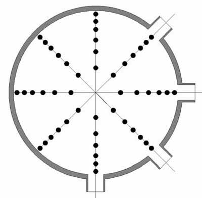
4. A typical 48-point coal pipe sample grid. Source: Storm Technologies Inc.
Usually, only two connections at 90 degrees are needed, and 24 points are sampled. Figure 4 is for short vertical runs of coal piping.
The first test conducted by a testing crew is the dirty air traverse. That test uses the same sampling points when measuring velocities in the pipes. By measuring the true velocity flowing through the pipe, guessing an unknown velocity, as required by the ASME test procedure, is eliminated. After the dirty air velocity test is completed, the coal is sampled. The sample is timed for accuracy by the technician controlling the sampling probe, while a second technician maintains a constant velocity through the probe for the pipe being sampled.
Through our experience, we have found that it is crucial to test pulverized coal fuel lines in the vertical rise only. Coal flowing through a pipe has a particular stratification in bends and on horizontal runs. Coal flowing around a bend will flow heavy on the outside corner of the bend, and in a horizontal run it will be heavy on the bottom of the pipe. Coal sampling data collected in a bend or on a horizontal run will not be representative. Figure 5 illustrates the proper and improper locations for coal sampling.
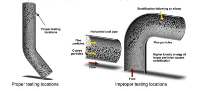
5. Where to take coal flow measurements on coal pipes. Source: Storm Technologies Inc.
Our approach is to collect coal samples at the isokinetic velocity, meaning that the sampler extracts the pulverized coal at the same velocity as it is flowing in the fuel line. Our sampler probes have a specially designed tip that improves the sample collection process. It is the same area opening as the ASME sampler, but the tip has a built-in internal deflector. This design eliminates the bouncing out or rebounding of large coal particles. Both large and small particles are captured once they enter the tip, producing a better sample for the coal fineness tests.
The tips of our probes are also much larger than those on a RotoProbe, which are 0.2 inch–diameter holes, or roughly 0.031 square inches each—slightly smaller than a pencil eraser. With wet coal, these tips often plug, adding to sample collection errors. Also, our probes can handle high-capacity fuel flow rates of up to 50,000 lb/hr per pipe and are virtually unpluggable. Our sampler is also designed with an internal orifice to measure the amount of air moving through the sampler. With the pressure drop through the sampler, this orifice is able to measure and control the velocity at the tip to equal the velocity of the flowing coal and air stream. We also have a back-up filter above the cyclone to trap any small particles to increase recovery rate, reliability, and overall accuracy.
Two Case Studies
The following two cases represent typical past experiences in pulverized coal–fired boiler testing results that illustrate the advantages of isokinetic coal sampling.
Case Study 1: MPS-89 Pulverizer with Eight Coal Pipes. Fly ash loss on ignition (LOI) was in the double digits, and there was repeated slagging in the upper furnace at the finishing superheater pendants. Coal fineness, when sampled from one of eight pipes, always would show 70%+ passing a 200-mesh sieve. Yet the fly ash samples were poor and fuel balance appeared poor. All eight pipes were then sampled and weighed and sieved using conventional testing methods (Figure 6).
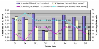
6. Data taken on typical pulverizers illustrates that only one coal pipe out of eight meets the absolute minimum specification for fuel fineness. Isokinetic sampling of each coal pipe allows the test engineer to identify relative pipe-to-pipe fuel balance, airflow balance, and air/fuel ratios that standard testing techniques can’t. Source: Storm Technologies Inc.
The worst single pipe was about 60% passing 200 mesh. The best pipe of the eight measured above 68% passing 200 mesh. On average, the pipes were about 65% passing 200 mesh, short of our standard of 75% minimum passing 200 mesh on a mass weighted average basis. The actual data are shown in Figure 6.
Coal pipe F9 on pulverizer B was the only pipe that met the original plant fuel specification guarantee of 70% passing 200 mesh, which is far short of the 75% minimum we use. Even so, fuel fineness and fuel distribution overall was poor, and it resulted in slagging, fouling, and higher-than-desirable fly ash LOI. Although the data appear to produce similar results without isokinetic sampling of all eight pipes, we would not have been able to obtain relative pipe-to-pipe fuel balance, airflow balance, and air/fuel ratios, which are critically important in identifying underlying performance problems and pulverizer deterioration.
Case Study 2: Raymond Shallow Bowl Mill Size #923. The fuel fineness by a single pipe ASME sampler was measured as 76% to 78% passing 200 mesh (depending on the pipe chosen for the sample). However, there is more to balancing coal pipes than simply achieving 70+% passing 200 mesh in a single pipe. Depending on the application, 70% may be acceptable and may be an indication of a properly functioning pulverizer. However, this standard approach does not take into consideration air/fuel ratios between pipes that will influence furnace combustion efficiency.
The data used for Figures 7 and 8 were taken using the isokinetic method when the primary airflow was biased up. In Figure 7, the fuel distribution was poor and fineness was imbalanced. The blue line in Figure 7 shows fuel fineness as measured, and the red line displays fuel balance as measured by the isokinetic coal sampler. High primary airflow caused the fuel balance to exceed the recommended ±10% deviation with the fineness deviation scattered across the four pipes.

7. In another plant, as-found test data show that coal pipe flow far exceeded the recommended ±10% deviation limit and that there was high variability in coal fineness. Source: Storm Technologies Inc.
8. After the individual pipe-to-pipe velocities were balanced using isokinetic coal sampling, the coal pipe flows maintained the desired 1.8 lb air/lb fuel ratio necessary for efficient combustion. Source: Storm Technologies Inc.
Figure 8 shows the fuel system after the primary airflow lines were balanced to maintain the desired 1.8 lb air/lb of fuel ratio. The optimized primary airflow to this mill brought the fuel flow balance to within a ±10% deviation (±5% would be better). Along with the balanced fuel flows, fineness across the mill also leveled out. The burners were then firing the average fineness of coal even though fuel fineness was poor. This balance in the mill caused better combustion in the upper furnace while balanced mills made for a more balanced furnace. Optimized burner belt combustion contributed to lower LOI, slagging, fouling, and reduced spray flows. The next step in this plant is to upgrade the mill to improve coal fineness to 75% passing a 200-mesh sieve.
Proper Coal Velocity Is Essential
Individual pipe-to-pipe velocities can be measured with the use of an isokinetic coal sampler, and the data collected is important in identifying burner issues, blockages, coal ropes, slow velocities that cause coal to fall out of suspension, and swing valve malfunctions. It is crucial to maintain velocities above 3,300 fpm to ensure that a coal particle is entrained in the air/fuel mixture. If velocities drop below, 3,000 fpm, fire or explosion in a coal pipe or pulverizer is possible if you don’t pay attention to all of the coal particle velocities and sizing in each coal pipe.
—Richard F. (Dick) Storm, PE is senior consultant for Storm Technologies Inc.