Managing the Catalysts of a Combustion Turbine Fleet
Natural gas–fired fleets comprising diverse turbine unit types are operating their units more these days because of the historic low price of natural gas. With increased operating hours, fleet owners are challenged to find the best ways to manage their SCR catalyst systems.
The majority of gas-fired combustion turbine (CT) fleets have made broad investments in selective catalyst reduction (SCR) systems in order to meet emerging air emissions regulations. Low natural gas prices have moved these plants to first in the dispatch queue in many regions of the U.S., displacing coal-fired plants. In fact, U.S. demand for natural gas is projected to grow 2.5% per year through 2035, effectively doubling the amount of natural gas used for power generation.
Many utilities are responding to the predictions that the relatively low natural gas prices we are now experiencing will become a “new normal” by either retiring selected coal-fired plants, thereby avoiding billions of dollars in environmental upgrades, or replacing those same plants with natural gas–fired equipment. Some utilities have negotiated with regulators a “refueling”—the replacement of a coal plant with a new gas-fired plant (a more efficient plant with much lower emissions). Others have “repowered” a plant, where the steam turbine side of the old plant is retained but the boiler island is removed and replaced with CTs and heat recovery steam generators (HRSG). Other utilities have not experienced load growth over the past few years and are able to defer the “retire or reuse” decision, for now.
One of the emerging operational decisions utilities and merchant generators with a large fleet of gas-fired combustion turbines must face in an era when gas plants are running baseload instead of cycling seasonally is determining the most economic way to manage NOx reduction SCR catalyst systems. In this article we discuss the process of economically managing a fleet of SCR-equipped CTs.
Diversity of Units and SCR
CTs burning natural gas are able to achieve NOx emissions and ammonia slip as low as 2 ppm when using an SCR catalyst with ammonia injection. In addition to baseload CTs used in the combined cycle plants discussed above, CTs are also used in simple cycle plants that are usually only called on to operate during periods of high electrical demand. Both, when outfitted with an SCR, present unique plant design challenges. A more recent trend is to build combined cycle plants with the capability to operate as either a baseload or peaker unit, thus presenting new challenges for both the steam generator design and the NOx emission control system.
In a combined cycle plant, the SCR modules are housed within an inner section of the HRSG at an optimized temperature location, typically 600F to 800F. A typical SCR catalyst bed housing appears as just another section within an HRSG (Figure 1).
 |
| 1. Typical combined cycle SCR. The SCR is a separate section located within the HRSG assembly where gas temperatures are optimal for SCR performance, typically 600F to 800F. Courtesy: Cormetech Inc. |
For simple cycle gas turbine applications, the SCR reactor is located in an expanded outlet duct immediately downstream of the turbine (Figure 2). The duct size is optimized to accommodate the SCR catalyst reactor performance. The short transition section from the turbine outlet to the SCR inlet poses challenges with the system design. The turbine exhaust flue gas temperature is often too hot to be efficiently treated by the SCR system. Many units rely on the injection of tempering air to cool the flue gas down to exhaust temperatures below 900F (±25F). An economic evaluation considering a number of design and operational parameters is performed to determine if tempering air or a high-temperature catalyst is the best selection. The evaluation must consider factors such as the capital and operating costs, operating hour limits, volume of catalyst, duct size and back pressure, purge fan versus tempering air fan cost, cost of the air distribution equipment, and so on.
 |
| 2. Typical simple cycle SCR. The SCR used on a simple cycle combustion turbine (CT) is located in an enclosure attached to the CT exhaust. Courtesy: Cormetech Inc. |
For both systems, the SCR catalyst system requires ammonia to be injected into and thoroughly mixed throughout the flue gas stream (Figure 3). To deliver a uniform supply of ammonia into the flue gas stream, a piping network or an ammonia injection grid (AIG) is installed upstream of the catalyst. The rate of ammonia flow is then regulated across the grid via a series of control valves. It is critical that the ammonia concentration within the exhaust gas be homogenous as it enters the SCR catalyst bed to prevent excessive slip of unreacted ammonia or, inversely, areas starved of ammonia, resulting in localized incomplete NOx reduction. Based on analyses of SCR operating data and catalyst samples, AIG and duct modifications may be warranted (see “Improving SCR Performance on Simple-Cycle Combustion Turbines” in the June 2010 issue of POWER or the archives at https://www.powermag.com).
 |
| 3. Typical HRSG ammonia injection grid. Ammonia reacts with the NOx in the exhaust gas stream over a catalyst to form molecular nitrogen and water vapor. If too much ammonia is used, unreacted ammonia may also leave the stack (ammonia slip). Courtesy: Cormetech Inc. |
Plan Plant Maintenance
Site environmental management for air and water systems is important to the ongoing operation at any power plant. These systems need routine oversight and must be maintained. Failure to properly manage them may result in permit violations and associated fines, operating restrictions, and bad publicity for the site.
Historically, many gas plants have been operated cyclically with extended dormant periods due to high natural gas prices and a varying demand for the electricity the plant provides. For plants with an SCR system, stopping and laying up the equipment may accelerate aging of the catalyst system components, increasing the importance of inspections and preventative maintenance planning.
SCR catalyst systems may run with little attention for three to five years and gradually begin to show signs of performance loss and system wear and tear. It is important to monitor the equipment condition and evaluate the performance demands against system capabilities to ensure reliable operation and avoid emergency outages. HRSG tube leaks, blinding of the catalyst inlet by dislodged liner insulation, plugged ammonia injection lances, seal integrity, or abnormal turbine conditions may trigger a change in the capability of the NOx emission control system to perform adequately (Figure 4).
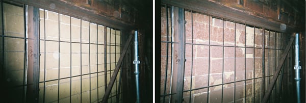 |
| 4. Keep your catalyst clean. Ash and other contaminants can blind the insulation layer around the catalyst. Shown are the catalyst modules when clean (right) and when the catalyst performance is reduced by blinded insulation (left). Courtesy: Cormetech Inc. |
Catalyst materials, by far the largest investment component of the SCR, can vary widely in their performance lifetime. The achievable useful catalyst life is a function of many interdependent and site-specific factors. The best approach to stretching catalyst life is to develop a responsible catalyst audit program to give routine feedback on catalyst perform and remaining life. Responsible planning and auditing can effectively reduce SCR operating costs and avoid large, unbudgeted expenditures. Your best approach is to make estimates of the SCR life-cycle cost as a management tool.
SCR Fleet Life-Cycle Management
For plant owners and operators, a baseline survey of each SCR unit within the fleet is the logical starting point for the overall catalyst management process and strategy. This fleet approach is a comprehensive and efficient way to provide an overall management plan that will surely lead to a lower cost structure and a more effective approach to decision-making than if each plant were to take on SCR system management independently.
A fleet SCR manager should be appointed who would be responsible for reliable compliance with all environmental air permitting requirements. That manager’s first responsibility would be to develop a comprehensive performance and material status baseline at each site and then to develop an ongoing preventative maintenance strategy (Figure 5).
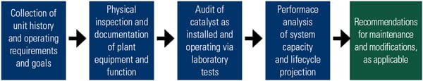 |
| 5. Survey says. A fleetwide baseline survey of SCR performance and material status is the first task that should be performed by a fleet SCR manager. Source: Cormetech Inc. |
One of the major challenges for the fleet SCR manager is to balance performance and operating costs. SCR equipment is custom manufactured for the unique demands of each plant, taking into account permit conditions and operating demands as envisioned for future years. SCR systems can achieve greater than 95% NOx reduction; however, when the efficiency of the SCR is pushed beyond 85% NOx conversion, and/or if outlet emissions are less than 5 ppm, it becomes much more sensitive to a number of independent system parameters.
These parameters include overall catalytic potential, effective ammonia injection/mixing into the flue gas stream, flue gas characteristics for inlet NOx, velocity, and temperature distributions. High-efficiency SCR catalyst system designs can successfully address these concerns through system modeling, flow correction devices, enhanced catalyst volumes, and robust ammonia injection grid design.
As plants upgrade, repair, or otherwise modify plant equipment in the future, the performance environment for reliable emission control can be affected. Understanding these potential impacts to the SCR system is essential and should be carefully studied before a modification is approved. For example, components of the ammonia delivery system may deteriorate over time or lack sufficient functionality to meet the demands of running with aging catalyst or tighter emission criteria.
A properly executed baseline survey conducted by a qualified catalyst management provider will serve to fully assess the current condition of each SCR unit in the fleet. These SCR system surveys must be site-specific, as each location will have its unique history and permitting requirements. The survey should begin with each site’s air permit requirements and goals (which can vary significantly, based on the age of the unit, geographic location, cost of ammonia, and more), identification of the SCR system supplier and equipment, and site operating history. Next, site maintenance records, catalyst test reports, and control room feedback should be assembled. Finally, a documented physical inspection of the SCR catalyst systems is recommended to help verify the historical records and equipment status.
SCR Management Plan
Following data collection and physical inspections at the plant, diagnostic laboratory performance testing may be needed to determine whether or not the catalyst condition is sufficient to meet performance requirements in view of field operating data and system requirements. It is important to verify that the testing is completed under conditions that closely match actual SCR system operating conditions and not under a set of theoretical or standardized design conditions. The sample should represent a typical cross section of the SCR, and the operating history should be known. A convenient method for sampling purposes is to incorporate an easily removable sample tray within the catalyst module (Figure 6).
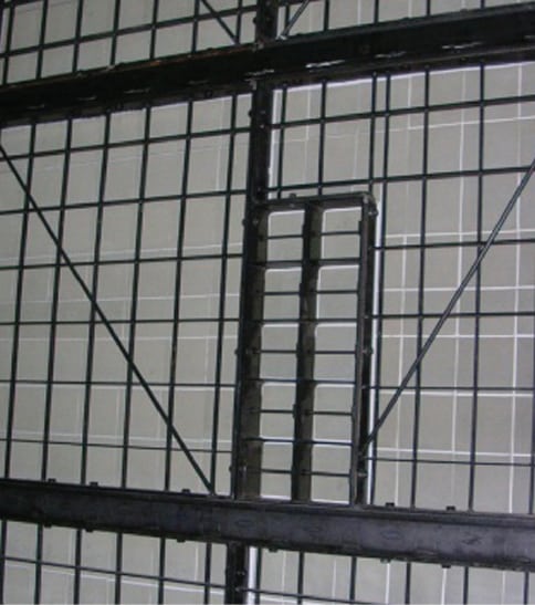 |
| 6. Take a quick sample. A sample tray installed on a catalyst module enables taking a catalyst sample very quickly. Courtesy: Cormetech Inc. |
The samples in the tray are quickly removed when the unit is off-line or during outages. This avoids rigorous drilling of the catalyst to extract core samples that are typically not required for units with homogeneous honeycomb product but may be recommended for units with alternate products and/or those that have localized impacts such as a tube leak. Tests are conducted in a controlled, laboratory environment on custom-built, validated SCR catalyst test equipment, allowing accurate determination of performance and comparisons of the sample catalytic potential with that of previously tested elements.
The assessment of field operating data determines the performance requirements of the SCR, the SCR operating conditions, the test conditions for the laboratory performance test, and the performance threshold. Changes in the field operating data relative to previous evaluations may warrant changing the test conditions or the performance threshold. An analysis of the field operating data in conjunction with results of the laboratory testing can determine if flue gas bypass and/or an ammonia to NOx imbalance is adversely affecting performance of the SCR.
Predicting the remaining life of a catalyst is tricky business. The usual approach is for an analyst to analyze the trends found with the laboratory test samples taken during a series of audits and field operating data over time and then compare those results with data from similar units, selected on the basis of operating history. From this comparison, a prediction is made of the remaining life of the catalyst during which the SCR is reasonably expected to meet performance requirements.
If the factors that affect catalyst deactivation do not remain consistent throughout the estimated remaining life, the future rate of deactivation will differ from the current observed trend. For this reason, periodic auditing to measure potential changes in the deactivation trend is recommended to improve the accuracy of the projected remaining life.
Other Recommendations
Some system improvements may be possible in systems nearing an end-of-life condition but with meaningful catalytic capacity remaining. For example, ammonia injection systems may be redesigned, modified, retrofitted, and/or repaired when performance gains are identified. In redesigning ammonia injection systems and associated ductwork, the catalyst management organization may employ computational fluid dynamic modeling as part of the optimization process. This optimization process can result in a reduction of ammonia usage and improved overall emission performance.
If survey results and diagnostic testing reveal that catalyst bed remedial measures or catalyst replacement is required, the fleet SCR manager has several options to recommend. SCR systems that contain catalyst with substantial remaining catalytic activity may be candidates for refurbishment of the SCR catalyst bed. This is a good option for a plant that has deteriorated seals and/or module wear and distortion that cannot practically be repaired by maintenance.
When the SCR catalytic potential has degraded and can no longer meet the plant’s needs, the entire SCR reactor bed must be addressed. In that situation, the options are usually full replacement, partial replacement, integrated reuse with new, or regeneration. Each method has its advantages and disadvantages that must be considered within the context of a given unit, plant, and fleet.
Logistics of individual unit replacement and integration within a given outage period must be considered at each plant. Early trials to prove long-term durability and applicability are recommended. Partial reuse may be applied by integration with an advanced module design, which can result in lower total pressure loss. Regeneration is the process of cleaning catalysts that are fouled by contaminants that are removable by a special aqueous-based chemical solution. This option may be considered if the catalyst deactivation mechanism indicates reliable recovery by the regeneration method and proven long-term performance can be guaranteed.
Every plant’s operations are unique, so a single catalyst cost estimate is not possible. Instead, take a fleetwide view and manage the life-cycle cost of SCR catalysts. This approach will keep catalyst costs low over the operating life while reliably meeting air quality limits. And don’t forget that routine audits and inspections will help ensure a long catalyst life.
— Terry McTernan, PE ([email protected]) is manager of project management for Cormetech Inc.