Focus on O&M (May 2007)
SYSTEM RELIABILITY
Cyber security and the grid
Too often, we think the consequences of cyber attacks are limited to disabled file servers, frantic damage control exercises by security personnel, and the loss of critical data. Although miscreants and thieves can cause all of these problems, we must add to our list hundreds of thousands of people stranded within cities, businesses shut down, phone systems disabled or taxed beyond their limits, and the eerie sight of miles of dark streets stretching between blocks of silent, uninhabitable buildings. It’s not hard to conjure up this scenario; we only have to think back to August 14, 2003.
That outage affected an area containing about 50 million people and 61,800 MW of electrical load in the states of Ohio, Michigan, Pennsylvania, New York, Vermont, Massachusetts, Connecticut, New Jersey, and the Canadian province of Ontario. Estimates of its total costs in the U.S. range between $4 billion and $10 billion. In Canada, gross domestic product was down 0.7% in August, there was a net loss of 18.9 million work hours, and manufacturing shipments in Ontario fell C$2.3 billion.
Though the causes of the 2003 blackout were not the result of a cyber attack, similar damages and cascading events could result from coordinated cyber intrusions into the infrastructure that monitors and controls North America’s interconnected transmission grids. Obviously, such events don’t just take a heavy financial toll and endanger the public. They also represent significant breaches in national security.
Entering this field of interconnected-system security in the U.S. are the Critical Infrastructure Protection (CIP) standards being promulgated by the North American Electric Reliability Corp. (NERC). The standards deal with sabotage reporting and identification of critical assets, securing critical cyber assets against intrusion, and physically securing access to the assets.
The deadlines for implementing NERC’s cyber security measures are still being finalized. But given the severity of risks to electric systems from cyber intrusions, it looks likely that enforcement of the standards will be put on a fast track, to begin late this summer or early fall.
The key CIP standard is CIP-002, which mandates risk-based assessments of both physical and cyber assets to determine how critical they are to system reliability. At press time, NERC declined to comment on the exact nature of such assessments. Staffers at the Federal Energy Regulatory Commission (FERC) have noted that they need to be fleshed out. They wrote, "while CIP-002-1 requires use of a risk-based assessment methodology, it does not provide direction on the nature and scope of that methodology, its basic features, or the issues it should address. The absence of more direction can result in the Requirement being unevenly executed, which may result in inconsistency and inefficiency."
Many of the persons responsible for reliability at firms that own and operate power plants are looking to their regional transmission organization or transmission provider for help in making the risk-based assessment. NERC’s "Security Guidelines for The Electricity Sector: Vulnerability and Risk Assessment" provides the following guidance: "A critical facility may be defined as any facility or combination of facilities that, if severely damaged or destroyed, would have a significant impact on the ability to serve large quantities of customers for an extended period of time, would have a detrimental impact to the reliability or operability of the energy grid, or would cause significant risk to public health and safety."
This type of identification implies an approach based on contingency analysis. However, unaffiliated generators do not have access to the transmission data that would allow them to run criticality studies for different scenarios for their plants. To gain a measure of control over the input and methodologies involved in the analysis, some independent gencos are considering hiring consultants to perform the studies. This would at least avoid leaving their designation in the hands of entities that may have a competitive interest in imposing costs on them.
—By Jim Stanton, POWER contributing editor and project manager at ICF International. He can be reached at 713-445-2000 or [email protected].
HYDRO POWER
Harnessing the Yangtze
Hydro power generators from Alstom Power Hydro (www.hydro.power.alstom.com) are converting the flow of a great river, the Yangtze, into electricity with the largest plant of any kind ever built, at Three Gorges in China (Figure 1).
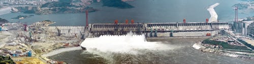
1. New Great Wall. The Three Gorges project’s greatest challenge was its sheer size—the dam is almost 1.5 miles wide. The entire plant is expected to be completed in 2009, 17 years after groundbreaking. Courtesy: Getty Images and Trelleborg AB
Alstom Hydro Power is based at the foot of the Alps, in Grenoble, France, where hydro power was born. Casimir Brenier began developing hydraulic turbines in 1854. Today, the company he founded is a subsidiary of Alstom Power and serves as the global technology center for Alstom’s hydro power business.
"The U.S. still has the largest hydro power capacity," says Jacques Brémond, supervisor of mechanical engineering at the Alstom Turbine Technology Center. "But Asia, led by China, is the fastest growing market. In Europe and North America, power generation exceeds the demands of the population, while in China and India more capacity is desperately needed."
China’s other great wall
Alstom is supplying almost half of the turbines and generators for the Three Gorges project, whose dam and plant were built for three reasons:
- To regulate the flow of the Yangtze. Its notorious floods have claimed an estimated one million lives over the past hundred years.
- To make the river navigable into the center of China.
- To create as much electricity as 18 nuclear plants and serve an estimated one-ninth of China’s current electricity demand. The project, when completed, will avoid having to burn 40 million to 50 million tons of raw coal each year.
The project’s greatest challenge was its sheer size. Compare the width of the Three Gorges (almost 1.5 miles) with that of a typical hydro plant dam (around 300 feet) and you begin to appreciate the scale of the undertaking.
A stunner of a runner
The main part of a hydro turbine is its runner (Figure 2), which converts the flow of water to mechanical energy. "The external diameter of the runner for the Three Gorges was 23% larger than any other we had produced before," says Brémond. "The runner is 35 feet across and 17 feet high."
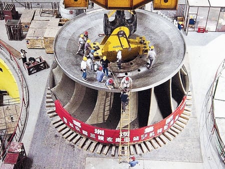
2. Superheavyweight class. It wouldn’t have made sense to build the runners in Alstom’s workshop in Grenoble. Weighing in at 425 tons, each runner would have been too heavy for the only bridge out of town. Courtesy: Getty Images and Trelleborg AB
The weight of a single runner—425 tons—precluded making any of them in Alstom’s workshop in Grenoble. After completion, they would have had to be transported over the town’s only bridge, which has a weight limit of 300 tons. Consequently, the runners were manufactured in a specially constructed workshop in La Ciotat in the south of France. They were then transported by sea to Shanghai and then transferred from oceangoing vessels to riverboats. It takes six of these riverboats just to carry the runner’s draft tube elbow.
In a gravity dam, the water flows down from a reservoir into a hydro turbine. It then enters the runner from one side via a spiral case, which distributes the water around the turbine. A distributor with adjustable wicket gates inside the turbine (Figure 3) controls the flow of water circulating within it. The energy of the water (head and flow) is then converted to mechanical energy (torque and rotational speed). Finally, the mechanical energy is transformed into electricity by the generator, which is on the same shaft as the turbine. Once the water has been through the runner, it is sent down a draft tube back into the river.
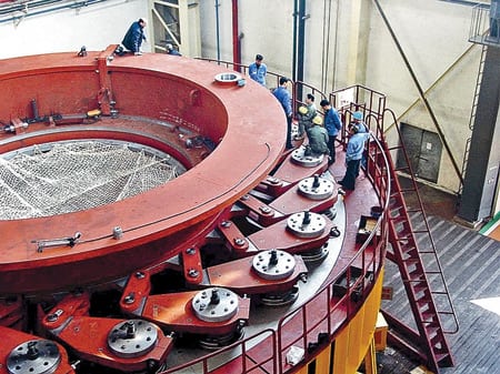
3. Wheel of fortune. A distributor with adjustable wicket gates inside the hydro turbine controls the flow of water circulating within it. Courtesy: Getty Images and Trelleborg AB
Given the size and weight of the runners at Three Gorges, run-of-the-mill bearings for rotating parts were out of the question. During the project’s early stages, Alstom considered specifying Orkot bearings from Trelleborg AB because it had used them successfully on smaller hydro projects for nearly 10 years. Yet, "we were unable to specify Orkot bearings on the left bank of the Three Gorges," says Brémond. "The customer requested that we use a bearing tailored to the application."
To satisfy Alstom’s customer, Trelleborg provided details of two independent tests on Orkot performed specifically for the application. "Based on the reports, we were increasingly confident about the performance of Orkot and decided to test it in the wicket gate lower brushes we built to refurbish a Francis turbine at the base of the Liu Jia Xia dam in China," says Brémond. "After a few more field tests, we pronounced the bearing fit enough to be used at full scale on turbines we supplied to the Alqueva Hydro Power Plant project commissioned in Portugal in 2004."
From skeptical to sold
Olivier Calemard handles the Alstom account for Busak+Shamban France (www .orkotmarine.us), a division of Trelleborg Sealing Solutions. "Ten years ago, the only products we supplied to Alstom were Orkot wear rings," he says. "When I first arrived at Alstom with my ‘plastic’ bearing, they laughed a little. It was so light compared to the metal ones they use, they couldn’t believe it would be strong enough to do a good job."
Getting Alstom’s business was an uphill battle, but Calemard never gave up. "We had to prove that Orkot could stand up to the task," he says. "Alstom would not risk specifying an unreliable component. The cost to replace a failed bearing is huge. It took time and lots of independent research and test data to convince them to use the product. Now, however, Alstom regularly uses it in the majority of their installations."
Orkot bearings (Figure 4) are developed and produced by Busak+Shamban’s manufacturing affiliate Trelleborg Sealing Systems Rotherham (UK). They are also manufactured at Trelleborg Sealing Solutions Eugene (Oregon) for the American market (www.tss.trelleborg.com). Due to the scale of the Three Gorges project, the two sites worked together to fill the order and shared technology. "We do benchmarking of processes across the two sites," says Barry Davies, general manager of Trelleborg Sealing Systems Rotherham, "to ensure product consistency. Working on a project like Three Gorges brings this requirement right to the forefront."

4. Fish-friendly, too. Most metal bearings need grease to make them work properly. At hydro plants, some of this lubricant ends up in the river. Orkot bearings use materials that have excellent frictional characteristics, eliminating the need for grease. Courtesy: Getty Images and Trelleborg AB
WASTE TO ENERGY
Hydraulic system overhaul
As the old saying goes, one man’s trash is another man’s treasure. At a waste-to-energy facility in Conshohocken, Pa., operated by Montenay Energy Resources of Montgomery County Inc. (www.veoliaes.com), many a man’s trash is being burned to produce an unending treasure of electricity.
Every day, Montenay Energy processes tons of household garbage and municipal solid waste at the 20-acre site. The waste is converted to thermal energy and then to enough electricity to supply 30,000 homes. In the process, the facility, which operates around the clock, reduces the volume of the solid waste by 90% and its weight by 75%. For every 100 tons of trash received, Montenay Energy generates more than 50 MW and produces just 10 tons of ash for landfilling. Many, including the U.S. Environmental Protection Agency, approve of this process as an alternative to using up precious landfill space.
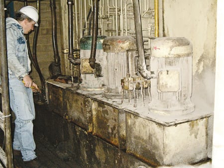
Recently, Montenay Energy upgraded the system that helps control the rate at which trash is fed into the incinerator. Many problems plagued the older hydraulics responsible for this portion of the process, but with the help of the Bosch Rexroth Hydraulics service group in Bethlehem, Pa. (www.boschrexroth-us.com), Montenay successfully incorporated the new equipment into its plant.
For years, Bosch Rexroth has managed the hydraulic systems used in waste-to-energy facilities from New York to Newark. A typical incinerator uses hydraulics to ram or feed the trash into a large boiler and to extract its ash. When Montenay decided to enhance its existing hydraulic system, plant O&M manager John Polidore consulted with Bosch Rexroth service engineer Keith Metz. The two had worked together on a previous project at Montenay to solve a problem involving corrosive hydraulic fluid. According to Polidore, he was so pleased with the results of their initial work and the ensuing relationship with Metz that he felt comfortable calling on Bosch Rexroth again for help on this major overhaul.
Not a grate design
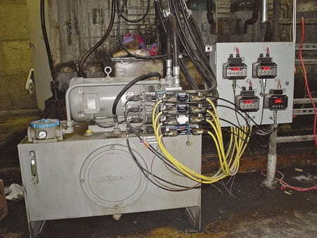
Montenay’s existing hydraulic system was designed in Germany and uses a main power unit with 24 submerged gear pumps (Figure 5). The gear pumps set the flow rate for multiple sets of identical cylinders that feed the trash into the boiler by controlling the movement of grates within the boiler. The grates are moving plates inside the boiler that shuffle the trash along as it burns.
5. From the Old Country. Montenay’s old hydraulic system was designed in Germany and uses a main power unit with gear pumps stacked together and submersed in tanks. The design makes the pumps difficult to access and repair. Courtesy: Bosch Rexroth Corp.
One problem with the old design, as Polidore knew and Metz quickly discovered, was that its fixed-displacement pumps move the grates and then stop them for variable periods of time, depending on process conditions. When the grates are stopped, weldments often occur that cause them to seize. After enough seizures, a grate must be taken out of service and fixed. Another problem with the design is that the gear pumps are stacked together and submerged in a tank, which makes them difficult to access and repair (Figure 6).

6. Six of twenty-four. The old system had 24 submerged gear pumps that set the movement rate for multiple sets of identical cylinders. Courtesy: Bosch Rexroth Corp.
The solution that Metz proposed to Polidore called for the replacement of Montenay’s 24 gear pumps with four Bosch Rexroth A10VS0-DR size 18 pumps, which are pressure-compensated. A controller maintains a constant pressure within the range of the pumps, so the pump supplies only the amount of hydraulic fluid required.
The pumps then pass the flow through Bosch Rexroth Model 2 FRE 6 proportional-flow control valves. Proportional flow control valves are two-way valves that allow an electrical signal to control the fluid flow independent of pressure and temperature variations. Each valve assembly comprises a proportional solenoid with an inductive positional transducer, a metering orifice, and a pressure compensator. The valves are controlled by Bosch Rexroth VT 5010 electrical amplifier cards with electrical position feedback. In Conshohocken, the cards are managed by the plant’s existing programmable logic controller.
Polidore accepted Metz’s proposal and Bosch Rexroth assembled a temporary unit at its facility and delivered it to Montenay as a complete power unit for testing. Airline Hydraulics Corp. (www.airlinehyd.com), a Bosch Rexroth distributor in Bensalem, Pa., helped test the power unit as it operated the entire feed system for one boiler, to prove that it could control the cylinders using the Model 2 FRE 6 valves and VT 5010 driver (Figure 7).
7. Test before ship. Airline Hydraulics Corp. helped Bosch Rexroth test the new power unit by having it operate the entire feed system for one boiler, to prove that it could control the cylinders. Courtesy: Bosch Rexroth Corp.
"Working together, all the components in the Bosch Rexroth hydraulics package have ensured cylinder synchronization," says Bill Hludzinski, an Airline Hydraulics sales engineer.
A final tweak
Once the testing was complete, Montenay asked Bosch Rexroth and Airline Hydraulics to redesign the entire power unit for each boiler. The unit now has four top-plate pump motor groups, each powered by Bosch Rexroth A10VSO pumps and new electric motors. Previously, it took six gear pumps to power one electric motor (Figure 8); now it takes just one. Along with supplying and installing manifolds, Airline Hydraulics and Bosch Rexroth were responsible for integrating the new unit into Montenay’s existing system and field piping. That completed the retrofit.
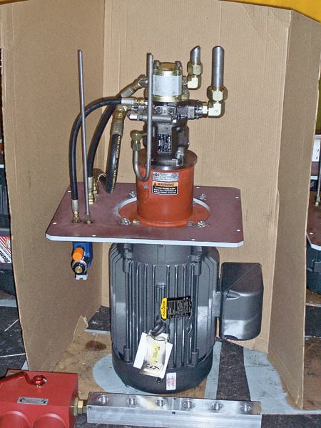
8. New pumps for old. The new gear pump design reduces from six to one the number of gear pumps per electric motor. In an operating plant, the unit is positioned upside-down, with the motor on top and the pump hanging down submerged in the fluid tank. Courtesy: Bosch Rexroth Corp.
Polidore was responsible for writing the front-end software program that converts the internal boiler conditions to signals that enable the hydraulics to react to changes in them. "The hydraulic system controls the motion of the boiler’s in-feed as a function of parameters such as temperature and pressure, explains Polidore. Metz adds that the pressure-compensated pump and the pressure-compensated proportional valve control the hydraulic flow throughout the cylinder cycle to achieve optimum feed rates and combustion quality.
Montenay operated the temporary test unit during the entire changeover process because, as Polidore says, "The plant cannot afford downtime, and the trash never stops coming." He says Montenay manages a facility in California where engineers are planning to upgrade their in-feed systems with the new Bosch Rexroth hydraulics design.
COMBINED-CYCLE PLANTS
O&M problems not caused by cycling
The steam system (the steam turbine and the heat-recovery steam generator) of a combined-cycle facility is an essential component of the overall plant. It is also the system that is least standardized because every facility has different thermodynamic requirements. Although gas and steam turbines are highly standardized and benefit from shared fleet experience, the designs of the HRSG and supporting systems at combined-cycle plants are almost always site-specific.
The first large combined-cycle plants featuring modern industrial gas turbines, such as the GE Frame 7 and Westinghouse 501F, entered commercial operation about 12 years ago. Newer plants, including those with steam-cooled gas turbines, built during the ordering boom of 1999–2004 have now accumulated enough operating hours to teach valuable lessons.
Most combined-cycle plants were designed for baseload service or limited seasonal operation. But changing economics of the wholesale power industry have dictated that the plants be run (and not run) in unintended ways, such as:
- Two-shift (daily) cycling.
- Long periods of operation at partial load.
- Use of alternate or lower-grade fuels.
- Extended lay-ups.
- Increased use of wastewater for cooling.
- The need to meet tighter air quality rules.
New modes, new problems
The consequences of frequent (daily) cycling of combined-cycle plants have been on the industry’s radar screen for several years. Operators have done a good job of solving problems such as thermal transients during start-ups and shutdown, boiler water chemistry excursions, and inadequate condensate drainage.
What the industry also needs to address, however, is the increasing damage and failures of pressure parts caused by accumulated low-level stress to which tubes and piping are subjected as plants age. The number of failures of these components, and the cost to repair them, are on the rise. Failures of superheater and reheater tubes at tube-to-header joints are becoming more frequent, as are leaks in economizers and preheaters.
Quality control problems with pressure-part welds were common during the 1999–2004 boom. The earlier defects did not reduce plant reliability, but now they are, because combined-cycle plants are being run in unanticipated ways. The more recent problems affect tube-to-header welds, welded stubs on headers, header end caps, and smaller bore piping. These have the potential to be major cost items in the future. A problem peculiar to plants with air-cooled condensers (ACCs) is that increased cycling can substantially increase the transporting of iron from the ACC to the tubes of the boiler/economizer.
Partial load operation
Running a combined-cycle plant for long periods at partial load lowers pressures in the low- and intermediate-pressure sections of the evaporator, lowers temperatures in high- and intermediate-pressure loops, and makes steam temperature harder to control. Some plants have experienced greater gas-side corrosion and deposition, increased flow-accelerated corrosion and erosion-corrosion, higher gas-side pressure drops (due to more deposits), and significant degradation of their heat rate.
Use of alternative fuels
In the past, burning fuel oil or another low-grade fuel in a combined-cycle plant was common only in countries where environmental regulations were not as strict as in the U.S. or EU. Today, higher-grade distillate fuels are being used during part of the year in many new plants. Firing waste fuels in gas turbines’ duct burners has become more common, and firing gasified pet coke or coal could follow.
Using nondesign fuels can significantly increase the potential for gas-side problems, such as corrosion and deposition. Burning fuel oil in duct burners raises radiation heating and the potential for hot spots and liner damage. For example, stress-corrosion cracking of cold-end preheater tubes has become more prevalent. Although burning even clean natural gas can produce the phenomenon, burning fuel oils and gasified fuels raises the risk of occurrence. Figure 9 shows the deposits on the preheater tubes of a plant that burns a low-Btu, high-H2S gas.
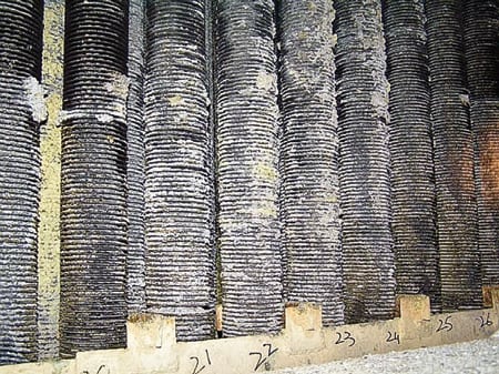
9. Asking for trouble. Preheater deposits caused by burning low-Btu, high-H2S gas. Courtesy: Tetra Engineering
Extended lay-ups
During periods of low electricity demand, many combined-cycle plants are put on extended standby, using wet or dry lay-up procedures. HRSGs’ experience with wet lay-up has generally been good because following modern industry guidelines can prevent serious corrosion problems.
For the other components of a combined-cycle plant, the greatest risk of an extended lay-up has been localized freezing, if the plant is in a cold climate. Many plants in extended lay-up have seen their tubes, headers, and piping freeze. Sometimes the damage was not immediately apparent and was discovered only during subsequent start-up. Figure 10 shows an area of economizer drains that is very difficult to protect from freezing.
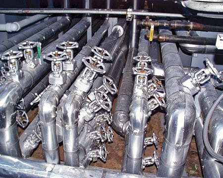
10. Drains not in Spain. Components at high risk of freezing, such as these drains, must be identified and protected during extended lay-ups. Courtesy: Tetra Engineering
Increased use of wastewater
Many combined-cycle plants now take their cooling water from lower-quality sources, such as processed municipal wastewater, agricultural run-off water, or brackish wells. This makes it more difficult for the facility’s water treatment plant to provide adequate supplies of water at various qualities to meet operating needs. Water treatment difficulties have increased waterside contamination and corrosion in evaporator tubes at several plants. Figure 11 shows underdeposit corrosion damage to the tubes of a high-pressure evaporator.

11. Hidden problem. Underdeposit corrosion damage in a high-pressure evaporator. Courtesy: Tetra Engineering
Tighter emissions control
Pollution standards haven’t just been ratcheted down for operating plants. Increasingly, the lower levels also must be met during start-ups and shutdowns. The performance demands on selective catalytic reduction systems for NOx control and on CO catalysts have increased, as has the risk of ammonia slip and deposition.
Supplemental firing systems also must comply with tighter pollution standards. The need to do so affects how they are fueled and their turndown ratios. The new focus on start-up and shutdown emissions is even affecting newer combined-cycle plants with steam-cooled gas turbines.
Figure 12 shows the dependence of CO emissions on load at a new power station. The high levels produced during start-ups limited the operating flexibility of the entire plant.
12. Roller-coaster ride. CO emissions are very dependent on turbine load. Courtesy: Tetra Engineering
—Contributed by Peter S. Jackson, PhD, PE ([email protected]), David S. Moelling, PE ([email protected]), and James W. Malloy of Tetra Engineering Group Inc.