Design and Testing of a Water Treatment and ZLD System
POWER has reported on zero liquid discharge (ZLD) technology (see, for example, “Fundamentals of Zero Liquid Discharge Systems,” Oct. 2011, available at https://www.powermag.com) and has discussed the industry’s operating experience with ZLD systems in the past (“Recycling, Reuse Define Future Plant Designs,” May 2006). Reducing power plant water consumption in the future remains an industry priority, so interest in ZLD and other technologies that reduce plant water consumption remains high, and POWER continues its coverage of the issue (see “Water Conservation Options for Power Generation Facilities,” p. 54).
In the following case study, Aquatech International Corp. discusses a water treatment system designed to minimize water usage and waste discharges, both liquid and solid, at a gas-fired combined cycle plant in California. Results of initial testing of its integrated water and wastewater treatment system with ZLD are also presented. The plant was commissioned in 2010, and the water system tests were conducted that December. The plant is nominally rated at 600 MW and uses dry cooling technology. The small amount of makeup water required by the plant is provided locally via canal.
Makeup Water Treatment
Raw water is chemically treated with sodium hypochlorite and coagulant prior to entering the stage 1 self-cleaning filters, where fine suspended solids and colloidal particles are removed. The self-cleaning filters act like guard filters, preventing large-size particle debris from entering ultrafiltration (UF) membranes (Figure 1).
 |
| 1. Water treatment system flow diagram. Treatment of the canal raw water employs prefiltration, ultrafiltration, reverse osmosis, and demineralization before the water can be used in the steam generator. Other water uses, such as makeup water for the evaporative coolers, can use water taken from one of the intermediate treatment processes. Source: Aquatech International Corp. |
Next, UF of the water is completed prior to storage in the 800,000-gallon raw water tank. The raw water tank is also the plant’s fire-fighting water tank. UF is a pressure-driven membrane separation process that separates particulate matter from soluble components. The advantage of UF membranes is that raw water can be disinfected without the use of excessive levels of chemical disinfectants, like chlorine. The flow through the hollow fiber membranes is an outside-in configuration. During the filtration process, solids accumulate on the surface of the membrane and must be periodically washed. The UF capillary hollow fiber membranes operate at approximately 90% recovery and at a flux rate of an average 25 gallons/square foot/day (Figure 2).
 |
| 2. Ultrafiltration membranes. UF membranes typically have pore sizes in the range of 0.01 to 0.10 µm and have high removal efficiency for bacteria and most viruses, colloids, and silt. However, the smaller the UF membrane diameter, the greater the pumping power required. Courtesy: Aquatech International Corp. |
Water treated by the stage 2 UF system is stored in the filtered water tank. This water is used to supply the plant’s potable water combustion turbine evaporative air coolers and the mixed-bed demineralizer via the two-pass reverse osmosis (RO) system (Figure 3). The treated water is then stored in the demin water tank.
 |
| 3. Reverse osmosis membranes. The UF-treated water is next treated by a reverse osmosis system to remove dissolved solids. Final treatment by a mixed-bed demineralizer will produce water suitable for use in the plant’s heat-recovery steam generator. Courtesy: Aquatech International Corp. |
All sources of plant wastewater are collected in the backwash wastewater tank, where water is treated and clarified through the Lamella clarifier. The clarified water is recycled back to the raw water storage tank for reuse. Sludge produced in the Lamella clarifier is dewatered in the filter press, and the dry solids produced are disposed offsite.
The filtrate produced by the filter press is also recycled back to the RO reject wastewater tank, as is the second-pass RO reject water, distillate from the crystallizer units, and evaporative cooler blowdown. Reject water from the first-pass RO is recycled through to the raw water storage tank (Figure 1). Reject water from the wastewater RO (WWRO) units is treated in the ZLD system.
The Zero Liquid Discharge System
The thermal portion of the ZLD system incorporates a mechanical vapor compression crystallizer to remove water from the high-solids waste stream and a plate and frame filter press to produce dry solids for disposal. In both processes, the filtrate streams are recycled back into the main water treatment system (Figure 4).
 |
| 4. Zero liquid discharge system flow diagram. The ZLD system receives the high-solids wastewater, concentrates the dissolved solids into a solid material suitable for landfill, and recycles the water. Source: Aquatech International Corp. |
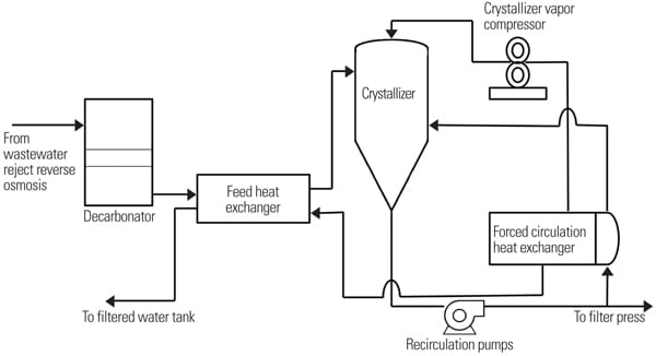
The crystallizer system is a forced circulation type of evaporator, which is specifically designed to precipitate and grow crystals in the brine as water is continuously evaporated.
Recirculated brine slurry is pumped through the forced circulation heat exchanger (FCHX), where it is heated above its normal boiling temperature with steam from the crystallizer vapor compressor (Figure 5).
 |
| 5. Concentrating the dissolved solids. The crystallizer, using carefully chosen chemical additives, captures the dissolved solids in the wastewater into brine slurry that can be processed by a filter press for easy disposal. Courtesy: Aquatech International Corp. |
The crystallizer is fed with WWRO reject water from the ZLD crystallization feed tank (not shown in Figure 4). Acid is dosed inline prior to the inlet of a forced draft decarbonator to convert scaling bicarbonates to CO2 and water in order to prevent scaling in the downstream equipment. The feedwater is then pumped to the feed heat exchangers. The heat exchangers preheat the feedwater by exchanging heat with the distillate streams from the crystallizer FCHX. The preheated feed streams are then fed directly into the crystallizer flash tank.
The superheated brine flashes as it discharges into the flash tank, which is operating at a slightly lower pressure than the brine side of the FCHX. The evaporation of water from the slurry supersaturates the brine slurry, and salts crystallize from the brine slurry to release this super- saturation.
The crystallizer concentrates the feedwater stream into heavy slurry of crystals using forced circulation evaporation technology. The design of the system is such that it overcomes the saturation limitations of a conventional evaporator: low-solubility scaling salts, such as calcium sulfate and calcium carbonate, and high-solubility salts, such as sodium chloride, sodium sulfate, and sodium nitrate.
A crystallizer recirculation pump is provided to recirculate the slurry at a high velocity through the FCHX tubes to suspend solids, avoid scale formation, and maintain high heat transfer coefficients. The flash tank is provided with sufficient residence time to allow the crystals to grow and reach super-saturation.
Flashed vapor is disengaged from the recirculating slurry in the flash tank. The vapor flows through an internal mist eliminator to remove suspended droplets from the evaporated vapor. The mist eliminator is intermittently washed with distillate to prevent the buildup of solids. Solids buildup will reduce the efficiency of the droplet removal and result in an increased distillate total dissolved solids concentration. A foam separator is used to remove liquid slugs that can damage the crystallizer vapor compressor. The vapor flows from the foam separator to the suction of the compressor.
The FCHX is heated by condensing steam/water vapor on the outside of tubes. The vapor generated by evaporation from the brine slurry provides the steam required. To utilize this steam, a motor-driven mechanical vapor compressor is used.
The density of the crystallizer recirculating slurry is monitored and controlled. On high density, the filter press automated valves open and slurry is fed to the filter press, where a dry salt cake is formed. The salt cake is then manually removed from the plates and falls into a dumpster.
Test Results
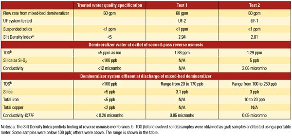
The water treatment and ZLD systems underwent 24-hour and 12-hour tests, respectively. Two tests focused on the performance of each of the two UF/RO water treatment trains, designed as 2 x 100% systems, each followed by a 12-hour test of one of the two crystallizers. The tests were conducted in December 2010 using canal water (see Table 1). The performance criteria were that effluent to the mixed-bed polishers (rented equipment) from each RO system could be maintained at 60 gpm under full automatic control and the quality of the water produced must meet the criteria shown in Table 2. Each equipment train was tested at full-load conditions. Test results are also shown in Table 2.
 |
| Table 1. Raw water quality analysis. Source: Aquatech International Corp. |
 |
| Table 2. Treated water specifications plus water test results. Source: Aquatech International Corp. |
In summary, the tests demonstrated that effluent to the rental mixed-bed polishers from each RO system could be maintained at rated flow under full automatic control (essentially hands-off operation for the 24-hour period). The product water from each UF system train also met the requirements for Silt Density Index, which predicts fouling of RO membranes.
The Lamella clarifier is intended to remove suspended solids from backwash cleaning of the UF cartridges, which occurs automatically throughout the day. The loading of suspended solids removed from the UF backwash was very low due to the low suspended solids load from the raw water.
The ZLD system was tested and produced salt cake sludge suitable for disposal as a solid that passed the Environmental Protection Agency paint filter test. The ability to receive and concentrate wastewater and produce brine under automatic control was demonstrated, as was the ability of the filter press to filter solids from the brine solution in the filter press feed tank. Auxiliary electric loads were also demonstrated to be below the guaranteed value.
Since the initial startup testing and trial runs, the plant has been performing as designed. The treated quality parameters of the filtered water, at the RO outlet, and at the exit of the mixed-bed demineralizer remain within predicted limits. The ZLD system, barring some maintenance on the preheater flash tanks, has produced salt cake suitable for disposal.
An upgrade plan is in place to increase the number of UF membranes in order to increase the available filtration area. The increased filtration area will also reduce the gallons of filtered water/day/unit membrane area produced in a effort to optimize the UF membrane cleaning frequency and increase system availability.
—Contributed by Ganesh Kamatkar ([email protected]), director of application engineering for Aquatech International Corp.