Could CAES Answer Wind Reliability Concerns?
As wind and solar energy capacity in the U.S. continues to grow, compressed air energy storage (CAES) and other bulk energy storage technologies will increasingly be used to help balance electrical supply and demand.
The United Nations wants countries to reduce their greenhouse gases 20% to 40% by 2020. In January, the U.S. committed to a 17% reduction. Japan’s Prime Minister Naoto Kan supports a 25% cut. Easy enough for the politicians to make the promises, but it is up to the power industry to do the hard work to make it happen.
Achieving those goals is made harder by the fact that the U.S. hasn’t built a new nuclear plant in decades, and hydroelectric dams are being torn down for environmental reasons. The big hope, of course, is wind. Over the past 10 years, the country has installed 33 GW of wind power capacity, with more than 10 GW of that total in 2009 alone. The next few years likely will see installations continuing at or above that annual rate. The problem is how to integrate all of this intermittent power into the electrical system.
“Power production from wind energy is variable and is predictable only to a limited extent,” said Bart Ummels, PhD, technical project manager, offshore for Siemens Wind Power in the Netherlands. “Since power generation must equal electricity demand at all times, this challenges power system operation.”
Denmark, for example, has the capacity to generate up to 30% of its power using primarily offshore wind turbines, but because high winds don’t necessarily coincide with demand peaks, the country sells as much as half of its peak production to Sweden and Norway. Similarly, the U.S. state with the greatest installed capacity, Texas, has to curtail wind production due to a lack of transmission infrastructure between optimum wind locations and load centers. And last year, billionaire investor T. Boone Pickens, founder of Mesa Power LP, delayed his planned 2,700-turbine, 4-GW Texas wind farm partly due to a lack of transmission.
This disparity between production and demand is renewing interest in using compressed air energy storage (CAES) as a cost-effective way to add wind and other intermittent power sources to the mix. Two CAES plants have operated successfully for decades, using excess electricity to compress air into underground salt caverns and then using that compressed air to power turbogenerators when demand and prices are high. Both plants use a single powertrain, with self-synchronizing clutches manufactured by SSS Clutch Co., which are utilized to select whether the motor/generator is to be used to drive the compressor or to generate grid power (Figure 1). Now dozens of other CAES plants have been proposed or are under development in an effort to balance electricity supply and demand.
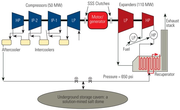 |
| 1. Under pressure. The only existing U.S. plant using compressed air energy storage (CAES) is located in McIntosh, Ala. A 49-MW Dresser-Rand compressor train pressurizes air in the 19 million-cubic-foot salt cavern to 1,100 psi and withdraws that air to power a 110-MW Dresser-Rand gas-fired expander train. It takes about 41 hours to compress the chambers; the generator can then operate at full capacity for 26 hours. The plant uses clutches from SSS Clutches to connect the compressor and expander with the motor/generator. Source: Energy Storage and Power |
Spreading the Load
At least on paper, large amounts of wind power can be smoothly integrated with dispatchable generation assets. The need for a very responsive power plant to smooth out the variations in wind generation in countries with growing wind resources is well documented. Some utilities with large amounts of wind energy on their systems have even built special plants that can “chase wind.” The typical technology for such plants is either a flexible combined-cycle plant (see “Top Plant: Langage Combined Cycle Power Plant,” Sept. 2010) or a gas-fired reciprocating engine (see “Top Plant: Goodman Energy Center,” Sept. 2009). In any case, gaining the fast response involves the cost of a new plant or the cost of cycling existing baseload units.
Another option is to develop energy storage, such as CAES. The energy being stored could, theoretically, originate with a large wind farm (which could store power during high wind generation/low power demand periods) or with any type of fossil-fueled plant that might store energy when cost and demand are low and feed it to the grid when, for example, wind generation is low relative to demand.
“A number of studies have been conducted in Europe and the United States,” said Ryan Wiser, a staff scientist at Lawrence Berkeley National Laboratory (LBNL) who leads and conducts research in the planning, design, and evaluation of renewable energy policies. “In well-designed electricity systems, where there is adequate flexibility, the cost of integrating wind into the utility system is somewhere less than $5 per MWh for wind power penetrations up to perhaps 20%.”
One such study, Ummels’ doctoral thesis, Wind Integration: Power System Operation with Large-Scale Windpower in Liberalised Environments (http://www.uwig.org/ummels_phdthesis.pdf), includes the results of two simulations of the Netherlands’ electrical systems. The first looked at electrical demand over a year, at 15-minute intervals, and calculated which power stations needed to be turned on and off at any given moment to meet electrical demand, or when power would need to be sold to or bought from surrounding countries. The second model looked at frequency stability at 4-second intervals to see how the system reacts to wind energy during circumstances such as storms. These two simulations were then combined to show what problems might occur with large-scale wind integration. Ummels says that utility systems are already designed to be flexible enough to compensate for sudden drops in supply, such as a power plant tripping off line, and should be able to accommodate the variability of wind generation.
“This Ph.D. research shows that existing power stations are able to set off the variations in demand and wind supply at any moment, provided that wind forecasts are taken into account,” said Ummels. “This conclusion is shown to hold even when wind power produces one third of annual electricity demand.”
LBNL’s Wiser said that the key to achieving that percentage of wind is to be able to draw on a variety of generation sources over a wide geographic area. For example, the Bluewater Wind project off the Delaware coast calls for backing up the offshore wind turbines with onshore peaker plants that generally run only when there is high demand.
“Having a lot of flexible generation in your system, natural gas or hydroelectric, helps lower the cost of wind integration relative to a scenario in which you don’t have very many flexible generating units,” said Wiser.
Westar Energy of Topeka, Kan., ran simulations before adding 500 MW of wind power to its generation mix. It found that using multiple wind farms in different areas would address some of the variability issues, but during July and August afternoons, when demand is highest, wind speeds were at their lowest. The model also looked at how wind variability would affect fossil generation sources.
“The model suggested that on average you are running a little higher on your heat rate curve for your fossil fuel generation,” said Paul Dietz, manager of quantitative analytics for Westar. “They are running a little less efficiently primarily because you have to have reserve capacity to handle the random output of the wind. We also realized we were firing our gas units a little more than expected, also in response to the variable wind.”
After doing the simulations, Westar went ahead and installed the wind turbines, finding that the actual output was a bit under, but close to, the simulations. “We have noticed that the actual performance of the units is a little less than the theoretical curves, since the windmills don’t have near the responsiveness that a simulation will give you,” he says. “The machines are slower to ramp up, so you get a little less power than expected.”
Smoothing Out the Peaks
Rather than distributing resources geographically, another approach is to use large-scale power storage technologies to balance supply and generation over time. Pumped hydro storage (PHS) is one technology that stores energy in the form of water, which is pumped from a lower-elevation reservoir to a higher-elevation one. Low-cost, off-peak electric power is used to run the pumps. (See “Bulk Storage Could Optimize Renewable Energy,” Sept. 2010 in our archives at https://www.powermag.com.) PHS has been around since the 1890s and is a significant contributor to production, with nearly 40 GW of capacity in the European Union and another 20 GW in the U.S. Expansion of PHS, however, is limited, due to the shortage of suitable reservoirs.
Battery storage is also a possibility. ABB has built a nickel-cadmium battery backup system for the city of Fairbanks, Alaska, which delivers 26 MW of load for 15 minutes (or 40 MW for 7 minutes) until the emergency generators can fire up. (See “Big Batteries Blooming,” Feb. 2005.) But nothing is yet feasible for truly large-scale deployment.
Flywheels are one more way to smooth out disparities in supply and demand. Flywheel energy storage works by accelerating a rotor (flywheel) to a very high speed and maintaining the energy in the system as rotational energy.
Other technologies under development include flow batteries, supercapacitors, and hydrogen fuel cells, but none of these is ready for prime time.
One technology that is proven, however, is compressed air energy storage. CAES is similar in concept to PHS, but instead of pumping water during off-peak hours, you are compressing air, storing it, and then releasing it to drive a combustion turbine during peak hours. Essentially, it separates the compression and expansion functions of a combustion turbine. Compression typically consumes about two-thirds of the energy created by a gas turbine (GT); therefore, a GT rated at 100 MW, for example, when separated, would have about a 200-MW compressor and about a 300-MW expander. CAES allows the compression to take place during off-peak hours, when supply is high and demand and prices are low. Then, during demand peaks, the full power of the GT can go to generating electricity rather than spinning the compressor.
“Gas turbine capacity represents approximately 30 percent of total CAES plant capacity,” says Dr. Michael Nakhamkin of Energy Storage and Power, who holds patents for a second-generation CAES system (CAES2) (Figure 2). “If the grid requires a 400-MW plant, the CAES2 design can be based on a 170- to 190-MW-class gas turbine such as GE’s Frame 7FA model. At the lower end of the spectrum, a 15-MW design can be based on a 6-MW-class turbine like the Solar Taurus 60” (Figure 3).
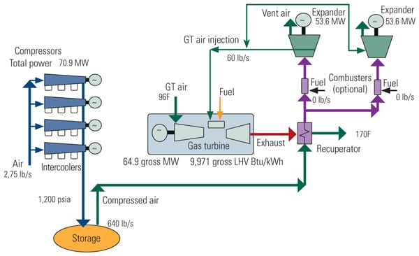 |
| 2. Making the switch. A CAES2 configuration based on the existing components from a conventional combined-cycle plant has been proposed by Energy Storage and Power. The CAES2 plant converts a 2 x 1 combined-cycle plant into a CAES2 system plus a 1 x 1 combined-cycle plant. In this figure, the power production mode produces 172 MW net with a 3,771 Btu/kWh net heat rate (LHV), according to the developers. Source: Energy Storage and Power |
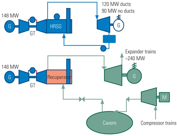 |
| 3. Major overhaul. For CAES2, a number of modifications would be necessary to a combined-cycle plant. In this diagram, green represents added components, red is for modifications, and blue is for existing equipment. Source: Energy Storage and Power |
Existing CAES Plants
The first CAES plant in the world was E.ON-Kraftwerk’s 320-MW plant in Huntorf, Germany, built in 1978. The facility uses two salt caverns with a combined capacity of 310,000cubic meters. Its 80-MW compressor can fill the caverns in 8 hours at a rate of 108 kilograms/per second (kg/sec) while the 320-MW turbine operates for 2 hours at an air mass flow rate of 417 kg/sec. The plant uses a single-shaft design. Model 340T clutches from SSS Clutch Co. are used between the generator/motor and the compressor on one side and the expander on the other. Intercoolers on the compressor reduce the energy needed for compression and, overall, the plant operates at about 42% efficiency. This plant has about 10% less capital cost than one with separate motor-driven compressors and turbine generators because it uses one foundation, one motor/generator, and one set of switch gears. Additionally, as a single-shaft machine, it can be inherently more efficient.
The second CAES plant was built by Power South Energy Cooperative in McIntosh, Ala., and went commercial in 1991. Its design is similar to that of the Huntorf facility. A three-unit, 49-MW Dresser-Rand compressor train pressurizes the 19 million-cubic-foot salt cavern to 1,100 psi and then withdraws the air to power a 110-MW Dresser-Rand gas-fired expander train. It takes about 41 hours to compress the chambers, and the generator can then operate at full capacity for 26 hours. Like Huntorf, it uses clutches from SSS Clutches to connect the compressor and expander with the motor/generator.
One difference, however, is that the McIntosh plant recuperates the waste heat from the expander’s exhaust and uses it to heat the compressed air, boosting efficiency by 25% and reducing the amount of natural gas burned. This makes the plant more efficient than simple-cycle gas turbines and, when gas prices are high, comparable to even modern combined-cycle GTs.
“The compressor train is about 80% efficient,” said McIntosh plant manager Lee Davis. “We have intercoolers between each stage of compression, and the expander section is also recuperated, so that keeps your heat rate down.”
The compressors generally get their electricity from a coal plant about 25 miles away, but when prices are right, the plant might buy from the grid or a combined-cycle plant. The unit is kept on a turning gear and can be synchronized and up to 110 MW in 14 minutes. Emergency starts can be done in 9 minutes. Because the expander does not have to drive the compressor at the same time, it can efficiently operate at loads as low as 20 MW. The efficiency, speed, and flexibility make it a good choice for providing peaking power. When the plant is neither compressing nor generating, the generator can be left connected to the grid, providing further benefit as a synchronous condenser in support of wind turbines that do not produce reactive power, or the grid in general, or to qualify for spinning reserve.
“The plant used to be seasonal, but now we run year round,” said Davis. “In the fall and spring we run as a backup unit or to help control the grid, and then we provide peaking power as necessary year-round.”
Both the Huntorf and McIntosh designs have shown that they can operate reliably for the long term. The Huntorf plant has seen as many as 375 compression and 450 generation starts in a single year, and the McIntosh plant has been through more than 2,200 compression starts and 3,600 generation starts since 1991. Last year it operated at 100% running reliability on compression and 98.15% running reliability on generation.
“The starts on the machine are far more than you get on any other kind of a peaking plant usually,” said Davis. “We use the [high-pressure] expander to start the compressor, so you have two starts in the day. And the way the dispatcher uses us to regulate the grid, you may have multiple starts a day, unlike a simple-cycle unit.”
CAES Development
Although it is has been 20 years since the last CAES plant was built, we soon will see more use of CAES to balance load and stabilize electricity prices.
“The driving force is the massive amount of renewable energy that is expected to come online,” said Jason Makansi, executive director of the Coalition to Advance Renewable Energy through Bulk Storage (CAREBS). “These plants can be built quickly, and they provide an unparalleled level of flexibility for grid management.”
Here are three examples of recent developments:
- In January, Pacific Gas & Electric received $50 million in funding (half from the Department of Energy’s American Recovery and Reinvestment Act funds) for the first stage of a 300-MW CAES plant in Kern County, Calif.
- FirstEnergy owns the rights to a CAES site at an abandoned limestone mine in Norton, Ohio, that has the potential of generating 2,700 MW of electricity. Municipal utilities, the federal government, and the state of Iowa are funding the Iowa State Energy Park, which, when operational, will pump the air into an aquifer 3,000 feet underground.
- Gaelectric is proposing CAES sites in Montana and Northern Ireland.
CAES technology is mature, and the Electric Power Research Institute estimates that there are suitable underground storage sites across 85% of the U.S. The natural gas industry now uses 500 caverns around the world to store gas near its customers and avoid shortages. The same strategy is needed for electricity.
“We need a series of large-scale, bulk energy storage facilities strategically located around the country, operating at transmission level voltages, not just for renewable energy but for arbitrage and general ancillary services,” Makansi said. “All you have to do is look at what natural gas storage has done for the natural gas markets: Over a 15-year period it has stabilized a highly volatile commodity.”
— Drew Robb ([email protected]) is a Los Angeles–based writer specializing in engineering and technology issues.