Big Bend’s Multi-Unit SCR Retrofit
Tampa Electric will soon complete a comprehensive selective catalytic reduction project on all four units at its Big Bend Power Station that will make Big Bend among the cleanest coal plants in the U.S. The project — the centerpiece of the company’s 10-year, $1.2 billion air quality improvement program — is on schedule to meet all of its air quality improvement goals by mid-2010.
Retrofitting a selective catalytic reduction (SCR) system at any operating plant is a major undertaking, but the retrofit project reaching completion at Tampa Electric’s four-unit Big Bend Power Station (BBPS) in West Central Florida was especially daunting. At one point, three units were under different levels of construction at the same time, with Unit 4 entering service in mid-2007 and the others following at yearly intervals. Another challenge: Much of the work was completed while the units were operating. Even more impressive is how the team accomplished this feat within the restrictive site confines. Imagine juggling basketballs inside a Mini Cooper, and you begin to get some sense of the challenge.
The project had its origin in December 1999, when Tampa Electric became the first utility in the nation to reach an agreement with the U.S. Environmental Protection Agency and the U.S. Department of Justice to resolve the federal agencies’ pending enforcement actions for alleged violations of the New Source Review requirements of the Clean Air Act. The resulting consent decree outlined a compliance plan to significantly decrease overall emissions from the company’s power plants. A key part of the plan was the installation of equipment to significantly reduce NOx emissions at BBPS by 2010. The reduction plans included converting Units 1, 2, and 3 from pressurized furnaces to balanced draft furnaces, comprehensive burner and windbox modification, overfire air changes, as well as adding SCR systems on each of the four coal-fired units (Figure 1).
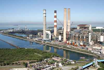
1. Go big or go home. Tampa Electric’s Big Bend Power Station (BBPS) will soon complete its fourth selective catalytic reduction system upgrade project in as many years. When complete, NOx emissions at BBPS will have been reduced by approximately 90% from 1998 levels. Flue gas desulfurization systems also remove 95% of the SO2 from the four coal-fired units. Courtesy: Tampa Electric
Big Bend unit details. Source: Tampa Electric
By the end of 2010, Tampa Electric will reduce systemwide annual SO2, NOx, and particulate matter (PM) at its facilities by 90%, 90%, and more than 80%, respectively, from 1998 levels.
At BBPS alone, Tampa Electric has invested $330 million in emission control SCR retrofits to make it among the cleanest coal-fired power stations in the U.S. To reduce NOx, Unit 2 SCR went into service in June 2009, Unit 3’s SCR went into service in June 2008, joining the already in-service Unit 4 SCR in achieving substantial emissions reductions at the station. Retrofit of Unit 1 with an SCR will be completed by mid-year 2010, reducing the total NOx emissions at BBPS by approximately 90% from 1998 levels. Flue gas desulfurization (FGD) systems, or scrubbers, remove 95% of the SO2 from the four coal-fired units.
BBPS consists of four pulverized coal – fired units, built from 1970 through 1983. Each unit fires a blend of high-sulfur midwestern bituminous coal and up to 20% petroleum coke. The sulfur content of the fuel blends is typically limited to produce no more than 5.4 lb/mmBtu of SO2. Typical of coal-fired plants of this vintage, the units were equipped only with modest forms of pollution control at the time of construction. Flue gas desulfurization, also known as scrubber technology, has been in use at Big Bend since 1985, when it was first installed on Unit 4. In 1995, the Unit 4 scrubber began scrubbing Unit 3 as well. Scrubbers for Units 1 and 2 began operation at the end of 1999. The SCRs for all four units were designed for outlet NOx levels that would ensure 30-day rolling average compliance under virtually all anticipated operating conditions and to assist in catalyst life longevity (see table).
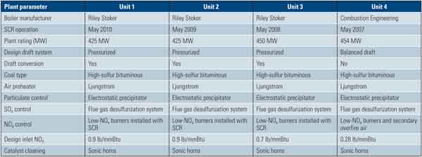
Big Bend unit details. Source: Tampa Electric
Many Construction Challenges
The SCR retrofit program at BBPS overcame particularly complex challenges, including overlapping construction schedules and a very congested project site. The 1,800-MW station has four units with different systems and configurations and an exceptionally tight plant arrangement.
One particular challenge posed by the SCR retrofits was developing cost-effective, reliable, and maintainable systems in such a way that the large columns and duct sections could fit within the confines of the existing plant that continued to operate during construction. For example, the first column set on the Unit 3 retrofit was 42 feet long, weighed 10.5 tons, and cleared the existing surrounding structural members by less than 1 inch on all sides.
Each of the retrofit projects was designed to accommodate variations in unit design while simultaneously standardizing on a baseline SCR system design. This standardized design could be efficiently modified for reuse on subsequent units, while facilitating ease of construction, minimizing field interferences and rework, and preserving sufficient maintenance access and laydown areas. A key goal was to ensure that each of the four units remained in operation as much as possible during construction while upholding Tampa Electric’s strong commitment to safety and meeting targeted safety goals.
Components Installed During SCR Installation
The SCR installation for each of the BBPS units was significantly more complex than the typical SCR retrofit project. In addition to the SCR reactor and ammonia injection grids, large-particle (popcorn) ash screens and intricate flue gas mixers were included as part of the NOx removal equipment (Figure 2). In addition, Units 1 through 3 were converted to balanced draft furnace operation, necessitating the installation of induced draft (ID) fans and the removal of FGD booster fans. This modification to the system design pressures also required evaluation and reinforcement of the boilers and associated flue gas ductwork (Figure 3).
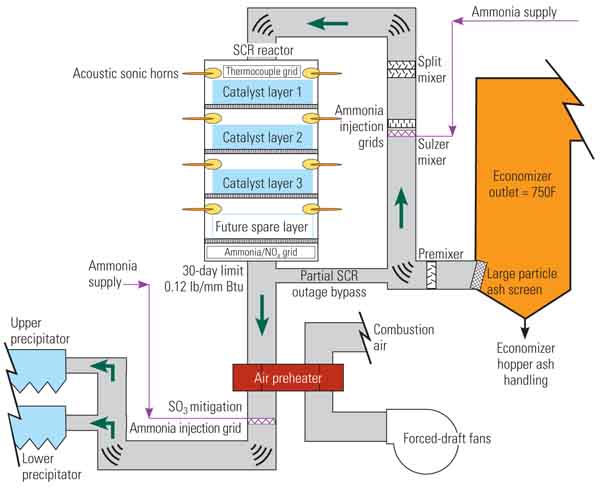
2. Complex upgrades. This schematic of Unit 3 illustrates the complexity of the system inserted between the economizer outlet and the preheat inlet. Design consistency for Units 1 through 3 was also part of the project requirements. Source: Tampa Electric
3. Balanced conversion. Units 1 through 3 were converted from forced to balanced draft furnace operation, necessitating the installation of induced draft fans as part of the SCR retrofit. Courtesy: Tampa Electric
All units have added or are adding an SO3 mitigation system that uses ammonia and an accompanying fly ash beneficiation system to remove ammonia from the fly ash. A controls upgrade was implemented or is planned for each of the four units. Units 3 and 4 also both had innovative economizer gas temperature control systems installed to provide greater flexibility and reliability while operating the units at lower loads. The Unit 4 system was a hot-water recirculation system developed by an alliance of Alstom Power and Tampa Electric. The Unit 3 system was a main steam let-down system developed by Tampa Electric and Sargent & Lundy (S&L). All of these additions were designed to be cost-effective, reliable, and to have minimal impact on plant operations during installation.
An anhydrous ammonia system was also installed to serve all four units. This system includes a 10-mile anhydrous ammonia pipeline supply to the station, a common unloading and vaporization area, and headers into the plant for both the NOx removal system and the SO3 mitigation system.
Contracting Approach
Tampa Electric proactively participated in the design, procurement, and installation of all the SCR systems and components that were part of the project. The company chose a multiple-lump-sum contract approach rather than a turnkey approach and retained S&L to perform the engineering/design and support the procurement of major fabrication and construction contracts. This approach allowed Tampa Electric greater input into the design and function of the SCRs, avoided the mark-ups often associated with large turnkey contracts, created well-defined scope packages — reducing contingencies for unknown scope, and enabled scope additions with minimal cost impact. Throughout each project Tampa Electric has successfully managed the lump-sum contracts to keep project cost growth from scope changes under 2%.
Restrictive Space for New Equipment
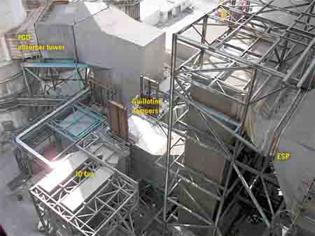
Most SCR retrofit projects face challenges related to site congestion, and the BBPS projects were no exception. In addition, the layout of each unit was unique; while all four units share a common turbine building and essential service systems, the back ends of each unit were not identical when originally designed (Figure 4).

4. Squeeze job. The extremely tight space available for the SCR upgrades on (from left to right) Units 1, 2, and 3 combined with the different unit back-end designs further complicated the SCR system design. Courtesy: Tampa Electric
Furthermore, the various electrostatic precipitator (ESP) modifications, FGD additions (including booster fans and new chimneys), and miscellaneous other alterations over time made each unit’s back-end configuration unique. Developing a general arrangement that maintained the required performance, safety, access, and constructability objectives was a time-intensive effort, involving substantial communication and interaction between S&L and Tampa Electric. High-precision 3-D modeling of the back-end configurations before and after SCR additions was essential (Figure 5).
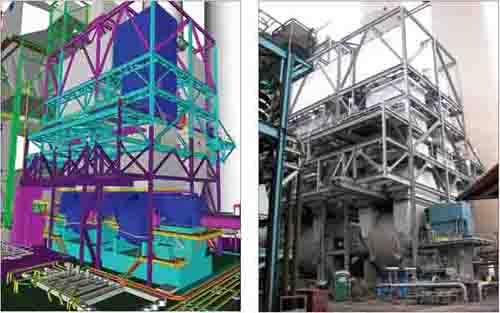
5. CAD tools were essential. On a job site where every inch of space must be accounted for, high-accuracy 3-D computer-assisted design tools were essential for design, construction sequencing, and future maintenance planning. Compare the 3-D design of the induced draft fan addition on Unit 3 with its as-built configuration. Source: Tampa Electric
To facilitate the design process, S&L performed numerous site walkdowns, including placing several personnel on site for approximately one year to meticulously model the existing structures and to create the conceptual arrangement for the new additions. Additionally, online model reviews were performed twice weekly with Tampa Electric plant staff to ensure that the design satisfied the project requirements discussed earlier. The strategy of on-site verification of existing conditions coupled with state-of-the-art 3 D modeling techniques permitted the SCR steel to be placed in areas that traditionally would have been considered too congested. For example, Units 1 and 2 share a common steel structure to support their individual SCR reactors, each measuring 60 ft x 44 ft x 48 ft high. The steel structure, supporting approximately one million pounds of catalyst per unit, uses eight columns for the two reactors.
Supporting the large ductwork, mixers, support platforms, and catalyst on four columns for each of these structures required massive steel columns. Space limitations not only restricted the number of columns used to support the SCR reactor but also affected the foundation design. It was virtually impossible to install the typical concentric foundation for SCR support columns, which required foundations to be designed off-center. The combination of auger cast piles, drilled piers, and micro piles mitigated the spatial constraints imposed by the existing equipment and structures.
The soil conditions were typical of Florida: silt and sand with low blow counts for the first 35 to 40 ft below grade that tended to settle significantly. Piles were driven to the rock below the sand (Figure 6).

6. Limited construction space. Selecting a viable crane location for the construction of the Unit 1 and 2 steel and SCR reactors was difficult due to exceptionally tight space. The selected location, between Units 2 and 3, required protection of the circulating water piping below because of the low ground bearing pressure. Prior to setting the crane, a 4-foot-thick concrete pad was placed, which was then covered with 7 feet of crane mats. Courtesy: Tampa Electric
The project demanded the new equipment foundations, steel structures, and ductwork be installed to the greatest extent possible while minimizing the impact to unit operation. To this end, on-site walkdowns, 3-D modeling, relocation packages, and effective communication between Tampa Electric, S&L, and the various contractors were imperative.
The 3-D modeling was also integral to the conceptual engineering, general arrangement preparation, interference checking, and detailed design. This directly influenced engineering time, erection costs, and construction scheduling. The model included all new support steel, ductwork, the SCR reactor, ID fans and associated equipment, large-bore piping and supports, cable tray, skid-mounted equipment, equipment removal paths, gallery and stairwells, underground utilities, plant roads, and miscellaneous other items affecting the design.
Relocation Packages
Because Tampa Electric used the multiple-lump-sum contract approach in lieu of a turnkey approach, equipment relocation also became an option to allow placement of support steel or equipment. Tampa Electric construction management and plant operations personnel were flexible in considering the relocation of existing plant components and structures, which significantly aided in and improved the design of the SCR steel structure and placement of the ID fans. Relocation packages included the emergency diesel generator, numerous underground utilities, numerous above-ground pipe utilities (including various steam lines and vent lines), and one large waste sump. The overall schedule allowed opportunity for timely equipment relocation.
Without the ability to relocate equipment, ID fan placement would have been extremely problematic. Because multiple sumps and underground utilities were at the back end of Units 1 through 3, relocation of these sumps allowed the ID fans to be installed much closer to the ESP outlet ductwork and in a better location relative to the FGD inlet ductwork. Relocation was managed at a very detailed level to ensure that it was completed as required to suit both the plant outage schedule and the project timeline. A relocation checklist was developed to track the following: new location, description of modification, outage requirements, responsible personnel, progress photographs, status of modeling, demolition drawings, relocation drawings, and notes necessary to complete the relocation package.
The tie-ins to existing systems were numerous. An analysis of the existing boiler steel for each unit was required to ensure adequate support of the tie-in duct to the economizer outlet. The existing boiler steel drawings were of limited availability, and the original design calculations from the 1970s could not be located, so on-site walkdowns were essential to verifying the existing boiler building steel configurations.
For the Unit 3 economizer gas temperature control modification, a main steam let-down system was provided to the first feedwater heater. That system reduced main steam from 1,000F and 2,415 psia to 700F and 685 psig through a unique pressure-controlled let-down valve and attemperator; feedwater was used for attemperation spray water. The let-down steam increased the feedwater temperatures at lower loads, thus greater operating flexibility of the unit was achieved while maintaining the targeted NOx reduction. The let-down system addition required detailed walkdowns of the existing steam systems in the heavily congested area below the turbine mezzanine. Modeling included the severe service control valves, alloy steel piping, drain lines to the condenser, and relief valves and associated exhaust lines.
Safety First
Safety is of the highest priority to Tampa Electric. For the BBPS SCR project, all contractors were required, at a minimum, to adhere to TECO’s written safety standards, including confined space, fall protection, and hot works standards. Due to Tampa Electric’s strong commitment to safety, more than 2.9 million man-hours had been completed as of December 2009 without a lost-time incident.
Last Project on Schedule
Today, Units 3 and 4 SCRs have been operating successfully to meet the NOx reduction targets and have been able to operate at or below the required 30-day rolling average for NOx emissions. No significant problems have been encountered on either unit with respect to the SCR and the accompanying equipment installations. Unit 2 is successfully meeting its project design NOx reduction after entering commercial service in mid-2009. The Unit 1 SCR outage is under way, and start-up is scheduled for spring of this year.
—R. Scott Bartz ([email protected]) is manager of construction for energy supply for Tampa Electric. Paul G. Hoornaert and Andrea N. Massa work for Sargent & Lundy LLC.