Water hammer and other hydraulic phenomena
Water hammer—or hydraulic shock —is an apt description of the sudden impact of a mass of fast-moving water on a piping component such as a valve or an elbow. It usually occurs in longer steam lines and is caused by the opening of a shut-off valve or the mixing of steam from one pipe with condensate from another.
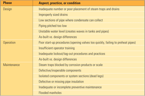
Several other thermohydraulic phenomena (Table 1) often are mischaracterized as water hammer. The observed damage includes mechanical damage, thermal shock, and high cycle fatigue. Water hammer happens rarely. But when it does, it can be destructive, expensive, or even fatal. Table 2 identifies the most common contributors to water hammer.

Table 1. Hydraulic and thermohydraulic shock events and where they occur. Source: Jonas Inc.

Table 2. Contributors to water hammer. Source: Jonas Inc.
Avoiding water hammer and similar events requires both a thorough understanding of their causes and contributing factors and following good design and O&M practices see box). As the four tragic case studies that conclude this article make clear, water hammer prevention should be given a higher priority at all power plants.
Considered as a whole, water hammer is a complex fluid mechanics process that may embody some or all of the following five phenomena.
Steam flow water hammer
This dramatic event can occur if condensate accumulates in low sections of steam piping. As steam flows over the liquid, it creates ripples, and if the level of condensate is high enough, the ripples may fill the entire pipe cross section (Figure 1). Under pressure, and with nowhere else to go, the ripples are transformed into a mass of water that the steam picks up and shoots down the pipe at up to hundreds of feet per second. The slug continues downstream until it hits an obstruction or restriction such as a valve, elbow, or orifice.

1. Forming a water hammer. If steam creates ripples on the surface of water in a pipe and the water level is high enough for the ripples to fill the pipe, the ripples can be transformed into a slug of water that the steam carries downstream at up to 136 mph. Source: Jonas Inc.
The maximum force at which the slug hits is the product of the water’s density and the square of the slug’s velocity. For a slug with a specific density of 60 lb/ft3 traveling at 200 ft/sec, the maximum impact force (pressure) works out to 520 psi. Added to the static pressure in the steam pipe, this force can exceed the rupture pressure of a pipe or a piping component.
Condensation-induced water hammer
Condensation-induced water hammer is an even more dramatic event. It may be caused either by steam entering a piping system that contains water (cooled condensate) or by the injection of water into a piping system containing steam.
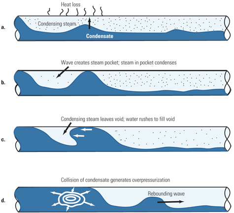
Figure 2 depicts the four-step sequence that causes condensation-induced water hammer. As condensing steam loses its heat to the pipe wall and cooler condensate (a), it changes phase from a vapor to a liquid. Working together, the condensation and flow of steam produce waves that build until they fill the pipe cross section, trapping steam between their peaks. The trapped steam then condenses rapidly (b). Because the resulting liquid occupies up to 1,000 times less space than it did as steam, the pressure in the void falls to a much lower level than that of the steam surrounding it. The void then collapses as the water, under steam pressure, rushes in (c). The collision of the water and condensate produces a local, pressurized pulse of water that rebounds down the pipe (d).

2. Four-step program. The four-step sequence that causes condensation-induced water hammer. Source: Jonas Inc.
The maximum force at which this pulse hits any downstream piping component can be calculated as the product of three terms: the water’s density, the velocity of the pulse, and the speed of sound in water. Assuming again that the water has a specific density of 60 lb/ft3 and a speed of 200 ft/sec, but now factoring in the speed of sound (4,300 ft/sec), the maximum impact force (pressure) works out to 11,200 psi. This is about 20 times greater than the maximum force of steam flow water hammer and well above the rupture pressure of any piping component.
Normally, the shock waves generated by a condensation-induced water hammer event do not cause catastrophic failure. Either the pressure in the condensate system is low, there’s not enough subcooling of the condensate, the steam voids are small, or sloping pipes prevent steam from becoming trapped. Catastrophes typically are caused by the mechanical failure of a piping system component, the pluggage of a trap by scale, or operator error. The severity of a condensation-induced water hammer event is a function of steam pressure, the amount of condensate subcooling, the amount of noncondensable matter remaining in the void, and the size of the void.
Deaerators and pressurized hot water vessels are a special case. In deaerators, the water and saturated steam are in equilibrium. Any rapid change in pressure or temperature can lead to rapid flash condensation or evaporation. Deaerators have imploded due to the vacuum generated by sudden steam condensation.
Water-flow water hammer
Water hammer also is possible in any water system, such as domestic and institutional plumbing. The familiar bangs it produces are caused by a mechanism similar to that in steam flow water hammer: a sudden decrease or stop of flow velocity.
Water piston
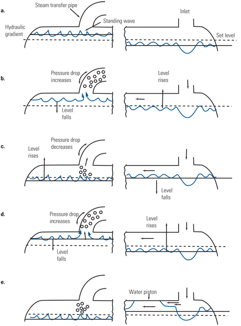
This is the common term for the unstable wave on a water surface (the formal name for it is Kelvin-Helmholtz instability) that can form in partially filled horizontal vessels such as in deaerator storage tanks. Figure 3 illustrates the complete five-step sequence of events that create a water piston. Briefly, the flow of water into a vessel can cause standing waves to form and fill its cross section, creating a piston effect. When there is a pressure differential across the vessel, the piston is propelled toward its end. When water piston occurs repeatedly, stresses can rise and fall and lead to corrosion fatigue of welds. The conditions for water piston can be predicted from the vessel’s design and operating data.

3. Water piston. A series of level oscillations occur at quasi-steady state until they form a water piston. The piston can repeatedly bounce between the ends of the vessel. Source: Source: R. Cranfield, L. Dartnell, and D. Wilkinson, "Solving Fluid-Flow Problems in Deaerators Using Scale Models" (CEGB Research, June 1982).
Most often, water piston-induced cracks in deaerators occur in either the heat-affected zones of its storage tank or in tank welds. The cracks are usually perpendicular to the welds, but parallel cracks, especially at the toe, also are common. In many vessels, the most serious cracking has been found to be parallel to the head-to-shell circumferential weld. Deaerators have failed catastrophically, with fatal consequences, due to weld cracking caused by water piston.
A survey of deaerators examined by wet fluorescent magnetic particle inspection (Table 3) indicates that the presence of water hammer (or water piston) is a likely cause of deaerator cracking.

Table 3. Deaerator cracking. There is a correlation between water hammer and deaerator cracking. Source: J. Robinson, "Deaerator Cracking Survey: Basic Design, Operating History, and Water Chemistry Survey" (Corrosion 86, Paper No. 305, NACE International, March 1986).
Water induction
When a slug, or even a small stream, of water enters a steam turbine, it is referred to as water induction. Typical locations include the blade rows downstream of extraction lines and the first stages of the high-, intermediate-, and low-pressure turbines.
Potential sources of the water include main and reheat steam piping, steam turbine extraction lines, gland seals, and turbine drains. Any water that is allowed to accumulate in the extraction steam and drain lines can get re-entrained in flowing steam. Water induction can also occur in interconnected steam piping systems. Usually, the phenomenon occurs during transient operation (start-ups, shutdowns, unit trips, and cycling); the results can be considerable and costly damage plus significant downtime. Most water induction events can be prevented by proper design and proper O&M practices.
Other hydraulic failure modes
The five phenomena discussed above do not constitute a comprehensive list of water hammer causes and effects. Other flow phenomena that can lead to equipment damage include:
- Shock waves generated by transonic flow, which can occur in valves and orifices whose pressure drop is above the critical pressure ratio (~2:1 for steam). These shock waves produce noise and induce vibration in pipes and valves, both of which can cause fatigue of steam turbine components.
- Condensation. The interaction of shock waves and condensation also can lead to fatigue by generating fairly frequent changes in pressure.
- Vortex shedding occurs in steam and water flows around obstacles such as heat exchanger tubes. The vortex periodically separates, typically at frequencies of hundreds of thousands of hertz. When the vortex shedding frequency is close to the natural vibration frequency of the obstacle, high-cycle fatigue may result.
- Cavitation refers to the formation of steam or air bubbles in liquid flow and the subsequent collapse of the bubbles on surfaces in the flow. It occurs when the pressure of water or other liquids falls below the saturation pressure. Cavitation is most likely in nozzle flows and in vortices where the static pressure is reduced by the dynamic pressure of locally high flow velocity.
Be safe, not sorry
Equipment damage and operator safety are put at risk by water hammer in any of its various forms. Although catastrophic damage may be a rarity (or perhaps just not yet visible), the risks involved are considerable. Following are four case histories that should convince you of that.
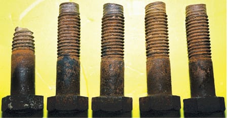
Activation of a heating steam line. When an operator activated a long, 8-inch heating steam line from a boiler house to a tank farm by opening a gate valve, a slug of water nowhere near the valve accelerated to the velocity of steam and broke off all of the bolts in the flange connection between the valve and the piping (Figure 4). The operator was killed.

4. Valve failure fatality. These broken and stripped valve flange bolts were the result of a water hammer event that cost the life of an operator. He had tried to "crack open" an 8-inch valve to admit steam to a cold pipe without first draining the condensate within. Source: Jonas Inc.
Newly built steam line. Condensation-induced water hammer occurred as workers attempted to drain condensate from a pressurized steam line as part of a procedure to put it into service. Two of the workers died and another two were injured. A post-mortem investigation blamed inadequate training, a poor procedure, and an improperly sized steam trap for the catastrophe. Had the workers drained the condensate from the line before admitting the pressurized steam, the event never would have happened.
Expansion joint failure. After a 185-psi steam system had been off-line for about eight hours, workers were asked to return it to service. But they failed to remove the condensate that had accumulated in the line before opening a 20-inch valve. The resulting water hammer event was severe enough to kill two of the workers and cause an explosion that ruptured an expansion joint, killing a pedestrian.
Deaerator storage tank head separation. Water piston was suspected of playing a role in the catastrophic failure of a circumferential weld at the head-to-shell joint of a deaerator water storage vessel at a pulp and paper plant. One head of the vessel (which was 12 inches across and 45 feet long) was blown off, and the remains of the vessel itself were found lodged in the side of a water tank a significant distance away. Three people working in the area at the time were killed.
—Dr. Otakar Jonas, PE, is president of Jonas Inc. He ca be reached at 302-478-1375 or [email protected].