Using Temperature- Measuring Indicators
Correct welding procedures are extremely important elements of the work done by the PSEG Central Maintenance Shop (serving Public Service Electric and Gas Co., PSEG, a New Jersey utility). We have, for example, a Critical Weld Inspection Program for high-temperature pressure piping whose goal is to identify cracks in high-temperature piping welds.
The stations work very closely with the PSEG Engineering department, based in Newark, N.J., to complete the inspections, and the Servco maintenance shop then makes the repairs. The shop commonly fabricates new spool pieces with dissimilar welds to replace existing ones.
There is always a high potential for failure cracking with transition welds joining dissimilar metals such as chrome and stainless steel. The weld procedure is to cut above and below the transition, do the more complex transition welds in the shop under shop conditions, and then replace the piece in the field by making welds between similar/same base metals.
How Weld Cracks Form
Weld cracking is usually caused by thermal stresses imposed on the weld metal and adjacent heat-affected zones. In welding carbon and alloy steels, cracking often occurs at the junction. The formation of hard, brittle regions within the weld occurs as the result of rapid cooling during welding. The presence of hydrogen can also cause weld problems.
Stress builds in the assembly as the weld metal shrinks as it cools and the weld metal is restrained by the surrounding colder metal. Also, heat is drawn away from the weld zone by the surrounding colder metal, accelerating stress formation. The rate of heat flow away from the weld is greater during welding of thick sections and in metals having a high thermal conductivity. In metals susceptible to quench hardening, such as high-carbon and alloy steels, the rapid movement of heat away from the weld area can result in the formation of hard, brittle regions.
The Importance of Preheating
One approach to reducing those thermal stresses is through controlled preheating of the pipe. Preheating is frequently required when welding metal parts used in the power industry. A successful weld unites the welding filler metal and the base metal into one solid part. A good weld is at least as strong as the base materials that are being joined.
With many materials, bringing the base metal “up to heat” before welding improves the chances of achieving a successful weld by reducing the danger of cracking and other flaws as well as achieving a suitable metallurgical structure and mechanical properties. As a result, rework is minimized and the integrity of the finished piece is enhanced.
Preheat temperatures are based on the type and composition of the metal being joined. The amount of preheating must be properly controlled in order to be effective. Preheating can help to minimize thermal gradients in the weld area, thereby reducing the resulting thermal stresses.
Preheating also reduces the rate of heat flow away from the weld, allowing more time for redistribution of thermal stresses, thereby reducing the tendency for cracking. In some steels it helps to minimize the formation of hard, brittle areas in the weld and heat-affected zones, improving ductility and crack resistance.
The presence of hydrogen greatly increases the possibility of cracking in the weld metal or heat-affected zone when welding carbon and alloy steels. Root cracks, toe cracks, under-bead cracks, and transverse cracks are all common, given sufficient thermal stress and the presence of hydrogen. In welding these materials, it is important to keep hydrogen away from the weld area. Hydrogen can come from electrode coatings, fluxes, base-metal contamination, and even hydrogen in the atmosphere.
ASME B31.1 lists preheating requirements for power piping. In general, as noted above, steels with higher carbon and alloy content, and greater thickness, need preheating. In some cases, the required temperature is only 50F minimum (a consideration for outdoor applications, but usually not important indoors). In many cases, however, preheat temperatures ranging from 175F to 400F are suggested.
Preheating is not necessary for 300 series stainless steels and nonferrous metals (such as nickel and nickel alloys such as monel, inconel, aluminum, or copper alloys). However, warming those metals as high as 200F may be desirable to remove moisture condensation and contamination. Preheating may be desirable for thick sections of high conductivity metals such as aluminum and copper.
Preheating can be very helpful in preventing the presence of moisture on the base metal surfaces and allowing hydrogen to escape from the weld area. Sometimes a post-weld bake (450F to 600F) is conducted to ensure that absorbed hydrogen is removed from the weld joint.
The need for preheating increases with the presence of these 10 factors:
- Thickness of parts being welded
- Lower temperature of the pieces to be welded
- Low ambient temperatures
- Lower heat input
- Higher speed of welding
- Higher carbon content of the steel
- Higher alloy content of the steel
- Difference in mass between the pieces being joined
- Complicated shape or section of the parts
How to Preheat
Oxy-fuel gas torches are the usual method of preheating large welded assemblies. Where more precise control of the preheat temperatures is required, furnace heating or use of electric resistance heating blankets or induction coils may be employed. With local torch heating or other rapid heating methods, it is important to not overheat the assembly.
It is also important to allow sufficient time to reach the desired uniform temperature throughout the thickness of the weld joint and surrounding metal. When using gas torches, it is important to prevent deposits of incomplete combustion products on joint surfaces or adjacent areas.
Accurate Temperature Measurements
The preferred method for determining that a joint has reached the desired preheat temperature is a simple one: a temperature indicator made of materials with melting points calibrated to a guaranteed accuracy of 1%, such as Tempilstik (Figure 7).
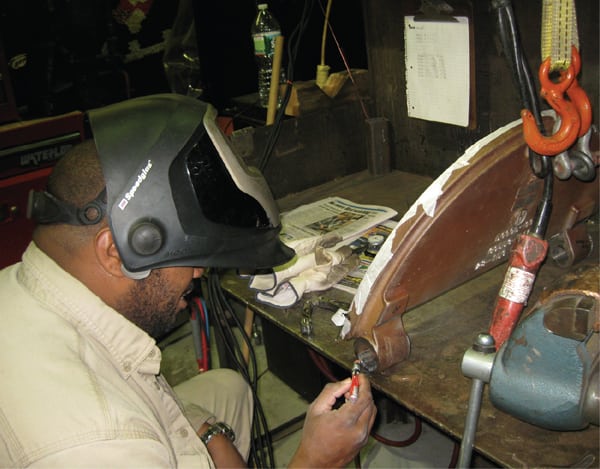 |
| 7. Marking temperatures. The welder is marking the metal with a Tempilstik temperature-calibrated indicator that is applied like a crayon. When the marker material melts, the metal has reached the specified temperature. More than 100 temperature range markers are available. Courtesy: Tempilstik |
The welder strokes a mark on the metal with a Tempilstik crayon as the metal is heated. The temperature indicators are made of materials with calibrated melting points. When the temperature rating of the selected indicator is reached, the dry opaque mark undergoes a phase change to a distinct melted appearance. Phase-change temperature indicators are preferred because they are accurate, simple to use, inexpensive, and make good thermal equilibrium contact with the surface of the material.
With Tempilstik temperature-indicating markers, no equipment set-up time, calibration, or recalibration is required to measure pipe preheat temperature, and no operator training or experience is necessary. The indicators are accurate within 1% of their stated temperature ratings measured in accordance with MTL-STD-45662. The materials used are calibrated on apparatus traceable to the National Institute of Standards & Technology.
—Contributed by Louis A. Chismar, Servco maintenance supervisor, PSEG Central Maintenance Shop, and Kenneth R. Stockton, PSEG training and development specialist, Sewaren, N.J.