Upgraded Boiler Feedwater Pump Improves Efficiency and Adds Flexibility
Times have changed. Not long ago, baseload units came online and went straight to full load for days on end. Now, those same units are being asked to cycle operations to accommodate for variable renewable energy resources. That can take a toll on equipment such as boiler feedwater pumps. One plant found that upgrading its pumps was the most-effective way to adapt to new operational realities.
As wind and solar power supplies have increased, conventional power plants have been asked to vary output to accommodate for intermittent renewable generation. For many units, that has also resulted in more cycling operation of boiler feedwater pumps.
At the Fort St. Vrain Generating Station in Colorado, greater pump cycling raised a few concerns. The plant’s original boiler feedwater pumps were not designed for frequent starts and stops, which created a higher risk of internal metal parts galling and increased the potential for pump seizure.
The Fort St. Vrain facility has a unique history. It was originally commissioned as a nuclear power station with an innovative high-temperature gas-cooled design. Unfortunately, the cutting-edge design created excessive operating costs and the nuclear plant shut down in 1989.
But that wasn’t the end. The plant was recommissioned in 1996 as a combined cycle gas-fired power station (Figure 1). The plant uses the original General Electric D8 nuclear steam turbine and three General Electric 7F-Class gas turbines feeding three Vogt heat recovery steam generators (HRSGs). The plant has dual exhaust stacks for simple cycle or combined cycle operation, which allows extraordinary flexibility in output from approximately 70 MW to more than 1,000 MW. This flexibility allows the plant to follow load swings that result as solar and wind power output rise and fall through the average day.
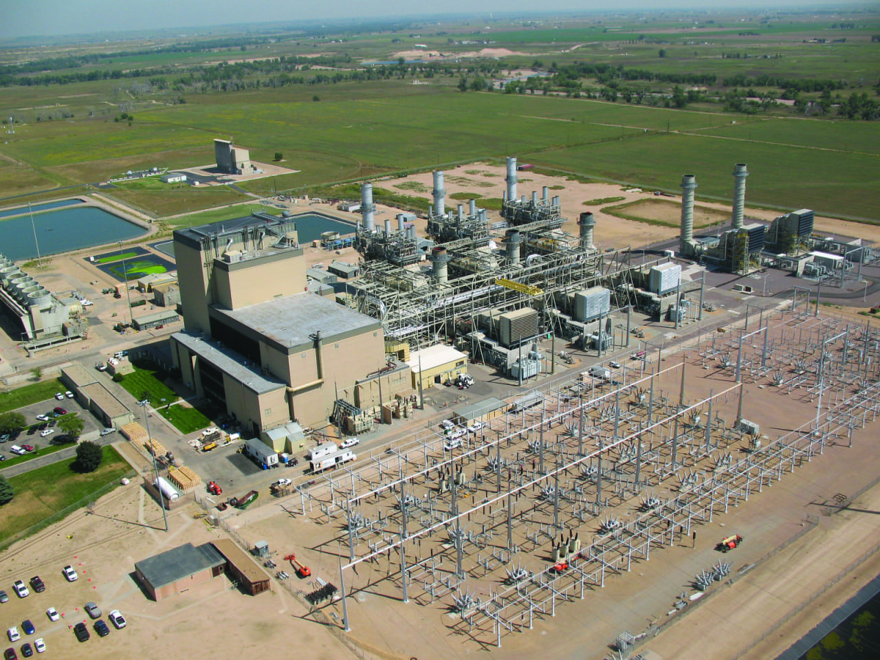 |
| 1. Fort St. Vrain Generating Station. The Fort St. Vrain nuclear power plant ceased operating in 1989 and was decommissioned from 1992 to 1996. The station was repowered as a natural gas-fired facility in stages between 1995 and 2009. Courtesy: Leif Bothun/Xcel Energy |
Motivation for the Retrofit
Each of the three HRSGs uses two 100% redundant, 10-stage, axially split boiler feedwater pumps (Figure 2) running at a typical operating temperature of approximately 260F and pressure of 2,700 psig. The pump internal seals (wear rings, center bushing, and throttle bushing) were originally constructed using stainless steel rotating and stationary parts. These components separate the high-pressure from low-pressure areas within the pump and directly impact pump efficiency and rotor stability.
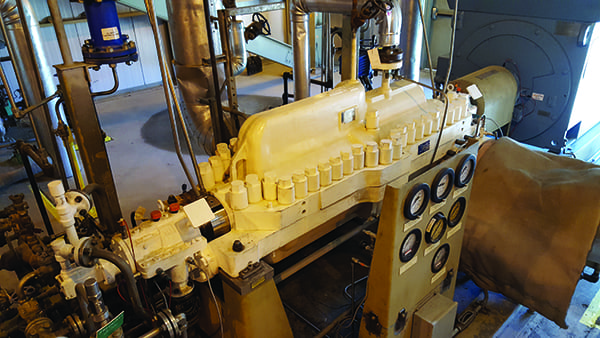 |
| 2. Fort St. Vrain boiler feedwater pump. Each of the plant’s three heat recovery steam generators has two 10-stage, axially split boiler feedwater pumps. Courtesy: Leif Bothun/Xcel Energy |
The original design also created a risk for galling or seizure at the internal seals. Because these are 10-stage pumps, the shafts are relatively long and thin. When the pump is not running, there can be a significant shaft deflection (rotor sag) at the center of the pump. The rotor sag creates potential for contact and galling at the internal seals, especially during a pump start. Once the pump is running, differential pressure across the internal seals creates a hydraulic force called the Lomakin Effect, which stabilizes the rotor and minimizes the contact between the internal seals.
The plant’s versatility is highly valuable to meet system demand; however, it creates some challenges. For example, the pumps in the boiler feedwater system are often forced to cycle multiple times per day. Because of the rotor sag, metal-to-metal contact can occur at each start or stop of the pump, creating the risk of a pump seizure. Adding to the challenge, the original equipment manufacturer (OEM) informed plant personnel that the pump was not originally designed for cycling operation. Rather, it was designed for steady-state operation—being online for weeks or months at a time.
Therefore, during a recent rebuild of the 31A pump, plant engineering and management requested that the repair shop evaluate and provide upgrade options that would allow the pump to better handle the constant cycling and avoid galling. Furthermore, if the pumps were going to be modified, the repair shop was also requested to consider potential performance upgrades.
One option was to continue using metal parts and standard clearances, but increase the difference in hardness between the rotating and stationary parts to reduce the risk of galling. Another option was to upgrade the stationary wear components to a composite material called DuPont Vespel CR-6100 and continue running stainless steel rotating parts. That option would eliminate the metal-to-metal contact points in the pump and effectively eliminate the galling and seizure potential.
With the risk of seizure minimized, the clearance between wear parts could also be reduced, providing an additional benefit of higher efficiency and lower operating costs. Due to the frequent cycling of the boiler feed pumps and the potential for performance gains, the plant selected the composite material for the stationary wear parts.
Accounting for Thermal Expansion Differences
In order for the application to be successful, important design details needed to be addressed. The first issue was accounting for the difference in thermal expansion between the metal components and the composite material. The coefficient of thermal expansion of Vespel CR-6100 is approximately 60% less than the coefficient of thermal expansion of the base metal components in the pump (see sidebar).
| The Importance of the Coefficient of Thermal Expansion
A very low coefficient of thermal expansion is required for a reliable upgrade to composites in boiler feedwater service because of the operating temperature and potential contact between rotating and stationary parts in the pump. The low coefficient of thermal expansion allows for dimensional stability as the pump heats up to operating temperature. More importantly, when contact occurs between rotating and stationary parts, frictional heat is generated. A typical plastic with a high coefficient of thermal expansion will grow, reducing the clearance between the parts, increasing the contact, and generating more heat in a rapid cycle toward component failure. A truly engineered composite with a very low coefficient of thermal expansion can withstand this frictionally generated heat, allowing the pump to survive through transient conditions without galling or seizure. |
The way to design for the difference is to install Vespel CR-6100 inserts with a press fit into metal holders (Figure 3). The press fit allows the composite insert to “follow” the metal part as it thermally expands, and it also prevents rotation of the insert. No additional anti-rotation pins or screws are needed.
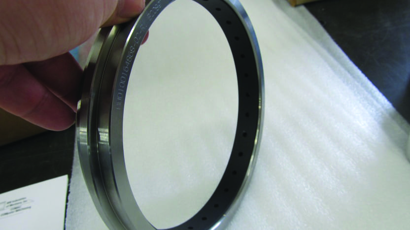 |
| 3. A marriage by design. To account for the difference in the coefficient of thermal expansion between Vespel CR-6100 and pump base metal components, the composite material is press fit into metal holders. Courtesy: Boulden Co. |
The inserts follow the metal part because the press fit creates a residual compression stress in the insert. The inside diameter of the insert will decrease at very close to a 1:1 ratio with the press fit. For the Fort St. Vrain pumps, the press fit on the case rings was 0.026 inch; therefore, the inside diameter of the insert decreased by 0.026 inch during the press fit.
As the pump is brought up to the 260F operating temperature and the metal holder thermally expands, the Vespel CR-6100 effectively mirrors the thermal expansion properties of the metal holder because the compression stress created by the press fit is reduced. The end result is that the composite insert expands at the same rate as the metal part and maintains the installed clearance at normal operating temperatures.
Addressing Differential Pressure Requirements
A second design requirement is for the composite insert to be able to withstand the differential pressure across the component. To account for that necessity, the metal holders were machined with a shoulder on the low-pressure side of the Vespel CR-6100 insert to prevent the composite material from being extruded by the differential pressure (Figure 4).
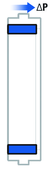 |
| 4. Lean on me, when you’re not strong. A shoulder machined on the low-pressure side (right side of this cross-sectional view) of the metal holder supports the composite insert (shown in blue on the drawing), holding it in place against differential pressure (∆P). Source: Boulden Co. |
In the case of the center and throttle bushings in the Fort St. Vrain pump, the maximum differential pressure across each component is 1,000 psi. Experience with composite materials over the years has revealed the possibility that high-pressure fluid can penetrate the press fit interface between the composite and the metal housing. Even though this is a rare occurrence, if it happens, it can create radial deformation of the composite insert and lead to premature failure.
To add a safety factor against this potential failure mode, the principals from the material supplier, Boulden Co., invented a patent-pending solution called the PERF-Seal, which uses a pattern of holes drilled through the composite insert (Figure 5).
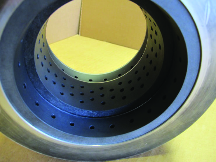 |
| 5. PERF-Seal design applied to the center-stage bushing. In some instances, high differential pressure can force fluid into the press-fit interface between the composite insert and the metal housing. The PERF-Seal design uses a pattern of holes drilled through the composite insert to eliminate the problem. Courtesy: Boulden Co. |
The holes balance the pressure between the outside diameter and inside diameter of the insert. This essentially eliminates radial deformation of the composite insert, allowing the reliable use of composites at much higher differential pressures.
The design has been validated using finite element analysis and in subsequent field trials up to 2,320 psi differential pressure. Further laboratory testing has also shown the design to reduce leakage across the seals by an additional 25% compared to a plain seal and to increase the rotor-dynamic damping coefficient of the seals by a factor of three to four times when compared to a plain seal at typical running speeds.
How Reduced Clearances Affect Pump Efficiency
The internal seals in the pump separate the high-pressure from the low-pressure regions. Due to the differential pressure, there is significant leakage across these parts, which decreases pump efficiency.
By upgrading to composite materials and eliminating the metal-to-metal contact inside the Fort St. Vrain pumps, it was possible to reduce the clearance at all of the internal seals—the wear rings, center bushing, and throttle bushing. Original and upgraded clearances are shown in Table 1.
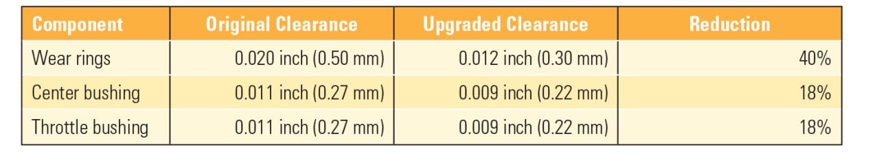 |
| Table 1. Original design clearance versus upgraded design. By reducing the clearance, significant efficiency gains were achieved (mm = millimeter). Source: Boulden Co. |
As noted earlier, testing of the PERF-Seal design has shown an additional 25% reduction in leakage across the components compared to plain, smoothbore components. The combination of reduced clearance and the PERF-Seal design in the upgraded pump led to a significant efficiency gain.
Before the results of the upgrade were clear, the site rebuilt another boiler feed pump, opting to return it to OEM specifications. Having two newly rebuilt pumps offered a great opportunity to compare performance between the original model and the upgraded design. The results are shown in Table 2.
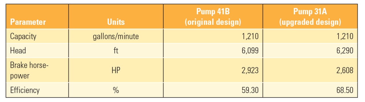 |
| Table 2. Comparing performance. Fort St. Vrain rebuilt pump 41B to original equipment manufacturer specifications and upgraded pump 31A with composite seals, which offered tighter clearances. Testing at maximum flow confirmed that the upgraded pump was nearly 10% more efficient while providing the same flow and higher head. Source: Dylan LaTorra/Xcel Energy |
Benefits Continue
Since the upgrade, plant operators have been happy with the pump. There have been no issues starting and stopping the pump repeatedly when the plant is asked to cycle. After two years of operation, there has been no noted increase in power consumption or decrease in performance of the upgraded pump.
Furthermore, Fort St. Vrain has experienced at least one added benefit. Previously, boiler feedwater pump motors would bump into and sometimes surpass their full-load rated amperage during hot summer days. Occasionally, the motors would overheat and trip. However, with the upgraded pump drawing less current, it has added a significant safety factor between full load and a tripped pump when it is needed most.
The savings in house power shouldn’t be discounted either. For a 3 x 1 combined cycle facility, if the operating pump in each of the three units is upgraded, the savings in electric house power alone is nearly 1 MW. For a utility to add this power to the grid instead of consuming it adds to plant profitability. ■
—Leif Bothun is senior operations manager at Xcel Energy’s Fort St. Vrain Generation Station and Robert Aronen is managing director with Boulden International.