Tuning Ammonia Flow to Optimize SCR Performance
The selective catalytic reduction system has become ubiquitous throughout the world of power plants. Emission control requirements are ever-more stringent, and the cost of excursions is becoming increasingly high. The key to staying under the regulators’ radar is precisely controlling the ammonia injected into the boiler. A new control strategy does precisely that.
Selective catalytic reduction (SCR) is the industry’s method of choice for removing the majority of nitrogen oxides (NOx) from flue gas, and it is a very effective method. The basic process used is the chemical reduction of NOx to nitrogen (N2) and water (H2O) by the reaction of NOx and ammonia (NH3) within a catalyst bed. The reaction itself occurs in a reactor chamber with a catalyst bed made up of replaceable catalyst modules and an NH3 injection system. Ammonia is injected into the flue gas before it reaches the catalyst. In short, the SCR system is quite simple, as there are no moving parts.
Ammonia Calculations
What isn’t simple is determining how much ammonia to use. The amount of ammonia introduced into the reactor is the critical control variable. If less than the amount required to reduce the NOx content to desired levels is injected, the reduction requirements will not be met. If too much ammonia is injected, then the phenomenon of ammonia slip occurs, where costly unreacted ammonia is exhausted to the stack. In some regions of the U.S., the amount of ammonia slip is also part of a plant’s operating permit restrictions. Tight control of the outlet NOx content is, therefore, a major concern for all plant operators.
The core requirement for achieving tight control of NOx is a robust control system that can nimbly respond to either a load or a NOx reduction rate setpoint change. It is well documented that the amount of NH3 injected into the SCR should be directly proportional to the amount of NOx entering the reactor. As a result, the SCR industry has developed a more-or-less standard method of modulating NH3 flow, as shown in Figure 1.
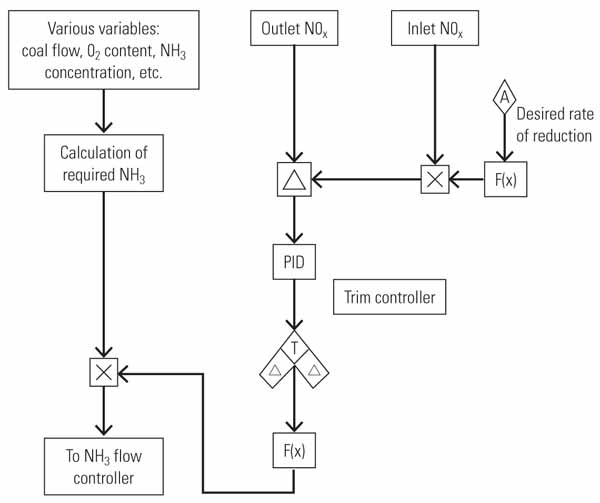
1. The standard. Most coal-fired plants use a more-or-less standard trim controller to determine NH3 demand to control NOx production. Source: Tim Leopold
In essence, this control scheme calculates the unit’s NH3 requirement for a given NOx reduction. The outlet NOx is then compared with a setpoint derived from some function of the product of the required reduction and the measured inlet NOx. This calculation varies in complexity from manufacturer to manufacturer and for different applications, but all are generally variations on this same control scheme.
A Decade of Experience
The first comprehensive NH3 injection control was developed by Babcock Power’s Dennis Twomey on Public Service of New Hampshire’s Bow Unit 2 in 1999. At the time, this was the best chemical control system available for the limited number of NH3 analyzers available that could be used in this tough, ash-laden environment. Another challenge was the few available, reasonably priced probes required by the control scheme. One of the advantages of a standardized process control design, like that developed by Twomey, is that it encourages suppliers of probes and analyzers to invest in standard designs suitable for an application. This approach also sets the groundwork for the eventual certified NH3 injection controls that are required by the U.S. Environmental Protection Agency.
Over the years, additional monitoring and control equipment has been added to this model control system to improve its performance. For example, others have added artificial intelligence systems or ammonia slip monitors and have used flame scanner data and other methods in an attempt to make this control loop more robust. All in all, these customized equipment additions to this control loop indicate to me that there is much room for improvement in the basic control system design when controlling outlet NOx and NH3 flow. Let’s get back to the basics.
Ammonia Control Details
Think of NH3 control another way. Remember that O2 trim of airflow and the trimming of fuel flow by the Btu master is standard in conventional boiler controls (see "Boiler-Tuning Basics, Part I" in the March 2009 issue of POWER and Part II in the May 2009 issue). One characteristic the two loops have in common is that they are both designed to operate at steady state. However, there are so many variables that can affect the amount of NOx generated by the combustion of fuel in the boiler that there is no way that the calculation can be considered to be fully dynamic.
As I pointed out in the earlier articles, a well-designed control system should not control airflow with O2 trim. With airflow control, there is an airflow controller that dynamically operates on the airflow. This ensures that the air is close to where it needs to be and allows the O2 trim to adjust the airflow rate in a predictable manner. Unlike the NOx control loop described above, it seems that the current approach to NOx control is to continue to add more expensive equipment to the control loop, thereby losing its basic attraction — simplicity. The trim controller seems to be almost an afterthought, a grudging acceptance that we can not know, or predict, everything.
So how is a trim controller different from a conventional controller? The reason I use the term "trim controller" is because the output from a controller, which ranges from 0% to 100%, then enters a function generator to scale the output of the controller. For example, perhaps 50% = 1.0, 0% equals < 1.0 (0.8 is typical), and 100% equals > 1.0 (1.2 is typical). The output of this function is then multiplied against some other variable. In airflow control, the O2 trim is usually multiplied against the airflow. The Btu correction is applied against measured coal flow. In NOx control, the outlet NOx trim is multiplied against the calculated NH3 requirement. In this example, the result is a family of curves of various slopes (Figure 2).
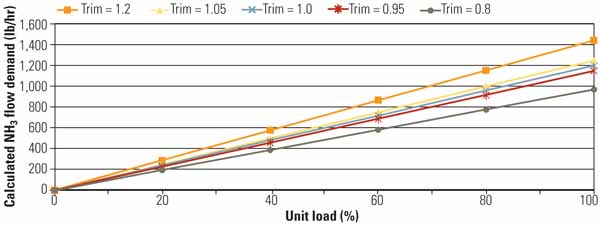
2. Effect of trim on calculated NH3 demand. Trim controllers are best used in steady state processes with fixed input variables. Coal combustion processes, in contrast, are complex, continuously changing, and difficult to predict. Source: Tim Leopold
The Effect of Trim on Calculated NH3 Demand
The impact of using trim control can be profound and explains why it is only used in specific applications in conventional boiler controls. For a given change in controller output, we expect to see a corresponding response. However, in Figure 2, we are actually adding an element of variability to the controls, in that for a given controller output we are changing the slope of the demand. This means that we assume a family of NH3 flow demand functions, depending on what has just occurred with the outlet NOx. This is why O2 trim and Btu compensation are, or should be, primarily integral only, and slow integrals at that. That is also why trim control does not do well in a load change or a boiler excursion.
Please bear in mind that the functions in Figure 2 are a somewhat simplistic representation of the complex calculation of the NH3 flow required for NOx reduction. The functions are not usually straight lines across the entire boiler load range. The calculation reacts to certain differing conditions in the boiler, such as fuel flow, O2 content, NH3 concentration, and possibly other measured variables.
However, the calculation must also consider certain differing conditions in the boiler that a trim controller is not designed to address, such as:
-
Boiler cleanliness (impacts firing rate)
-
Secondary air damper positions
-
Burner tilt positions
-
Exhaust gas recirculation
-
Fuel distribution in the furnace
-
Air/gas distribution in the furnace
-
Windbox-to-furnace differential
-
Pulverizer control parameters that affect primary airflow and coal fineness
This means that if these boiler conditions change, then the calculated value changes. However, depending on the output of the trim controller, the amplitude of the reaction will vary because the calculation can only look at a few, finite number of measured variables and not these unmeasurable factors inherent in the boiler environment.
For the sake of argument, let’s agree that a controls approach akin to O2 trim may not be the best choice for NH3 injection for NOx control. Instead, we are trying to hold tight control on a variable with a large range where a complex calculation methodology is available. The control scheme can easily be constructed as a cascade control loop: outlet NOx controller provides the setpoint to the NH3 flow control. This sounds like superheat temperature control to me. Figure 3 illustrates a proposed NOx control portion of such a cascaded loop controller.
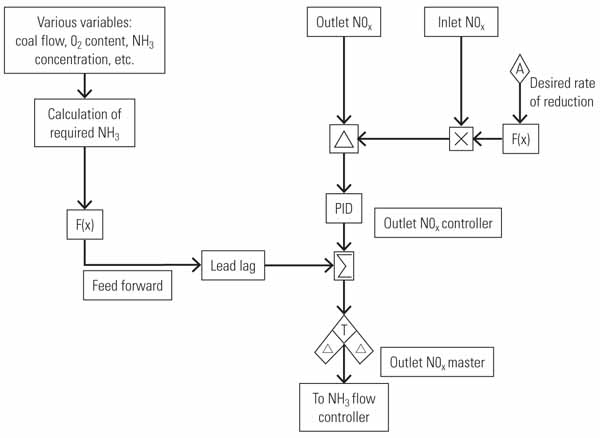
3. New and improved. A better approach to holding tight control of NH3 is a cascade control loop where the outlet NOx controller provides the setpoint to the NH3 flow control. Source: Tim Leopold
I know that some of you are thinking: This is a catalyst reaction. That is, the SCR is a second- or third-order reaction, and from Controls 101 we know that a second-order reaction cannot be controlled with a simple PID (proportional-integral-derivative) loop. However, introduction of the calculated NH3 demand as a feedforward allows us to control outlet NOx quite well. Let’s take a look at how this new approach to controlling NOx works in practice.
Applying the New Control Concept
Figure 4 shows the data from a test of the new approach to controlling outlet NOx and NH3 flow just described. The logic outlined in Figure 3 was implemented at the Gainesville Regional Utilities’ Deerhaven plant. However, the standard industry approach was not eliminated (because of warranty issues); instead, the new NOx control approach was implemented with a slow transfer switch to allow us to go from one scheme to the other to compare the system’s response.
First of all, the calculated ammonia requirement devolves to the line trim = 1.0. Therefore, the reaction to changes in the boiler conditions as seen by the controller is always the same. Again, this is important in controls. We are now able to shape the effect of the calculated NH3 demand (the feedforward) by use of a function generator and maybe a derivative kick. The outlet NOx controller in this approach is stronger, more dynamic, and more robust. The end result is a control loop that can be better tuned to control the outlet NOx and the injected ammonia.
In Figure 4, the NOx trim controller transforms to the outlet NOx controller. The transfer is begun at the time shown by the first vertical line. Then, fortunately for the sake of this illustration, the operators, unbeknownst to me, increased the reduction requirement from 85% to 90% (second vertical line). The new controls were tuned with only preliminary estimates, yet it can be seen that control of the outlet NOx quickly becomes more stable.
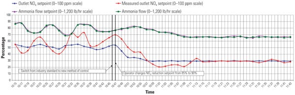
4. Real-world testing. The new control strategy was implemented at Gainesville Regional Utilities’ Deerhaven plant with excellent results: The plant can now control outlet NOx to within 2% of setpoint from 40% to 100% of full load, compared to the previous 5% to 6% using the old control logic approach. Source: Tim Leopold
After seeing the results of the new control loop’s response to load and coal changes, Babcock Power eliminated the industry standard solution and has implemented the changes suggested above. The Deerhaven plant has exercised this control loop from 40% to 100% load with less than 2% NOx outlet swings. This is considerably better than the 5% to 6% NOx outlet swings with the old logic standard approach.
Giving Credit Where Due
I first developed this approach for improved NOx control about eight years ago at Mercer Station in Trenton, N.J. I later learned that a very similar solution was independently arrived at by AEP engineers while working with Tim Nahrwold of Babcock Power.
The SCR projects that were a partnership between AEP and Babcock Power started with the standard NOx control loop. But with further testing and tuning, it was determined that a new method was needed, and AEP began to review options. The method that was finally implemented at AEP was independent of the inlet NOx analyzer with NH3 demand derived from boiler load (feedwater flow in these supercritical units) versus boiler historical NOx output from the economizer outlet as a feedforward to the NH3 controller. Regardless of how the setpoint is arrived at, the controller using the NOx outlet analyzer is a very robust and dynamic part of the control loop.
I would like to acknowledge the assistance of Duane E. (Donny) Thompson III, engineer IV with GRU Energy Supply, and Timothy A. Nahrwold, senior staff engineer, Babcock Power Inc., during the preparation of this article.
—Tim Leopold (tim.leopold@hotmail .com) is a field service engineer with ABB and has more than 20 years’ experience tuning controls on power plants around the world. His book, You Can Tune a Boiler But You Can’t Tuna Fish, was published in March 2009, and is available at www.amazon.com. Visit his blog at http://timthetuner.blogspot.com.