Top Plants: Hirakud Power, Sambalpur, Orissa, India
Owner/operator: Hindalco Industries Ltd., a company of Adityabirla Group
Hirakud Power uses environmentally friendly circulating fluidized bed (CFB) combustion technology to produce electricity for one of the world’s oldest aluminum-smelting operations. This "captive power plant" has engineered a number of technical fixes to its original boiler designs to improve plant reliability and reduce outages and boiler repair costs. It also has made strategic investments in upgraded machinery to reduce auxiliary power consumption. In addition to an excellent environmental track record, as evidenced by being Asia’s first ISO 14001 (BS 7750) – certified power plant, Hirakud Power has solidified its position as an industry leader in CFB boiler operating experience and efficient power production.
The Indian Aluminum Co. (INDAL) slowly began to blossom in the post-independence era by seizing the opportunity to build an electricity-hungry aluminum smelter in the state of Orissa, the easternmost Indian province, which is blessed with abundant and inexpensive hydroelectric power generation. INDAL’s first smelter, christened in 1959, was capable of producing up to 10,000 tons/year (tpy).
Steady growth by INDAL began to stress the state-owned hydroelectric supplies in the early 1980s. Power interruptions became more frequent and, consequently, resulted in lost aluminum production. The price of electricity was also rising fast. The answer was clear: The only reliable electricity supply is one that a company owns and operates. Plans were developed by INDAL to construct a new captive power plant (that is, a plant built for and owned by an industrial firm).
In 1994, INDAL established its first coal-fired power generation system, rated at 67.5 MW, to provide an uninterruptible power supply to its adjoining aluminum smelting operation (Figure 1). Fortuitously, one of Asia’s largest coal deposits is located nearby, making the fuel choice simple. In 1999, Aditya Birla Group took over INDAL from the Aluminum Company of Canada and merged it with its flagship unit, Hindalco, a year later.
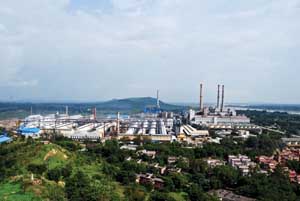
1. Reliable electricity needed for growth. Hirakud Power is a “captive power plant” that supplies all the electricity needed by Hindalco’s aluminum-smelting operation next door. The plant was built and expanded when government-run hydroelectric plants could not supply enough reliable and reasonably priced electricity to support the growing aluminum-smelting plant. The coal mine that supplies the plant’s fuel is located nearby. Courtesy: Hirakud Power
Aluminum production continued to rise, as did Hindalco’s need for reliable electricity. Aluminum production increased from 30,000 tpy to 143,000 tpy by 2009 with the commissioning of new smelting units, which also argued for the installation of additional power generation units. Generation rose from 67.5 MW to 367.5 MW in 100-MW increments in 2005, 2006, and 2008 (Figure 2).
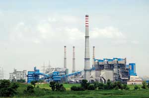
2. Modern boiler technology. Hirakud Power operates four captive power units, shown in the foreground, consisting of 11 circulating fluidized bed combustion boilers and four steam turbines, with a total capacity of 367.5 MW. Courtesy: Hirakud Power
Coal is supplied by Hindalco’s own captive mine at Talabira and is fed to the boilers after suitable sizing by the plant crushers. The four units receive raw water from the Hirakud reservoir through gravity. The plant uses a dense phase pneumatic dry ash disposal system.
Of note, Hirakud Power is the first captive power plant in Asia to achieve ISO 14001-1996 certification (then BS 7750) for its high-quality environmental management system, certified by Bureau Veritas Certification (formerly BVQI), the world’s leading certification body. Hindalco’s environmental policy requires the company to be "committed to continuously improve our energy performance in all our activities, products, and services so as to make it environmentally sustainable for future generations."
Different Boiler Designs
Hirakud Power is recognized as a progressive electricity producer and is very active in ensuring that any waste products from the coal-fired units are recycled whenever possible or are properly disposed of. This attitude of taking pride in the small environmental footprint of its plants began with the installation of the first circulating fluidized bed (CFB) boilers in India in 1994. The Unit 1 boiler system is configured as a 2 x 145 tons per hour (tph) hot cyclone CFB, with the two boilers designed by Ahlstrom Pyropower and supplied by M/S Isgec John Thompson with a single steam turbine generator. Units 2 through 4 each consist of a 3 x 155 tph cold cyclone CFB boiler supplied by M/S Krupps India Pvt. Ltd. and a single 100-MW steam turbine generator. The four units together give Hirakud Power one of the world’s largest fleets of coal-fired CFB boilers at a single plant.
There are significant differences between the two CFB cyclone designs. The hot cyclone design has a much higher fluidizing velocity (6 to 7 m/s) and has full recirculation of fuel and bed material (more than 63 microns), causing increased erosion of refractory and steam generator tubes and significantly more insulation on the hot recirculation piping.
In the hot cyclone the combustion temperature is controlled by the rate of recycling fine material. Hot fine material is separated from the flue gas by the hot cyclone and is partially cooled in a loop seal, where a low-velocity fluidized bed is maintained and cooled using a Roots blower. The cooler fine material is then recycled to the dense bed. The cold cyclone design has a much lower fluidizing velocity, thereby saving on forced draft fan power, and a very steady bed temperature due to the controlled recirculated cold ash. The cold cyclone design also enables much quicker boiler start-up.
Hot Cyclone Design Problems
Hirakud Power has gained much hard-earned hot cyclone boiler operating experience over the 15 years since Unit 1 commissioning. Most of the major operation and maintenance issues directly relate to the high-temperature, high-velocity recirculating bed material. What follows is a digest of the types of problems encountered plus a short description of the final repairs completed.
Warping and Erosion of Hot Cyclone Vortex Plates. Each of the two cyclones consist of 11 stainless steel plates inside the cyclone that act as anti-vortex plates — 10 are 1,865 x 635 x 12 mm, and the smaller one is 1,865 x 457 x 12 mm — held in place with special hardware. Unit 1 has experienced erosion of the plates, and several have actually fallen out of their mounting points. There’s also been bending; failure of the refractory in the cyclone neck, roof, and bull nose area; and burnout of the loop seal nozzle cap on a number of occasions.
To fix these problems, the plant staff added hard facing in a zigzag manner with LOMELT-201, a stabilized 18/9.5 Cr/Ni/Cb electrode, on each of the stainless steel plates, thereby improving the plate’s temperature range up to 1,100C. All the other accessory parts were welded with Inox-CW welding rod, good up to 1,000C. Additionally, each of the 12-mm vortex plates was upgraded to 16 mm and 310 series stainless, as was the loop seal bed nozzles and bed nozzle column pipes. An adequate expansion gap was added between each of the plates to eliminate the bending experienced earlier, and a 25-mm ceramic fiber blanket was inserted between the plate and refractory.
Erosion in Pressure Parts. Hirakud Power uses coal with 40% to 45% ash content; hence, the threat of boiler tube erosion is always present. Erosion was observed early in the life of Unit 1 boilers in the hanging economizer tubes; economizer, superheater, and convection tube return bends; and evaporative tubes on either side at the exit of the combustor and combustor water tubes, among other locations.
The plant staff developed a unique solution for the hanger tubes: add a three-element overlapping semicircular stainless steel shield. Baffles were also added to reduce the impact of flue gas, and stainless steel protective shields were added to the lead coils of each group. Unfortunately, experience showed that the erosion then just shifted to the next row of coils, so all of the exposed tube bends were protected with shields.
The economizer header outlet tubes (three rows) presented a tangential surface to the flow of erosive gases and also had to be protected with welded-on tube shields. In the economizer, a thin layer of metal spray was tried but was unsuccessful in reducing erosion. Subsequently, a thin layer of erosion-resistant refractory was applied with good results.
Erosion in Air Preheater Tubes. The initial approach used to control erosion in the air preheater tubes was the same as that used in the boiler pressure parts: weld on a metal shield to the top row of tubes in each bank. However, as the flow path between the side wall and tubes is small, the higher-velocity gases caused higher rates of erosion farther back in the air heater assembly. Next, the original tube materials were substituted with higher-corrosion-resistant ASTM A 423/95 CorTen steel with higher nickel content. Unfortunately, although erosion in the middle of the tubes was eliminated, the ends of each tube (next to the wall penetration) continued to experience excessive erosion. Repairs were made using stainless steel sleeves on the ends of the tubes, which didn’t significantly reduce unacceptable tube erosion; the repairs resulted in slower rates of erosion, but erosion all the same.
The air preheater erosion was more toward the rear side, approaching the electrostatic precipitator, than on the front side, facing the boiler. There seemed to be a serious non-uniformity present in the flow path velocities at the inlet of the air preheater. Subsequent pressure drop testing at different locations in the air preheater was completed and, along with the air preheater dimensional data, was entered into a computational fluid dynamics computer code for further evaluation. The simulation results indicated that without baffle plates (the original design), there is significant variation in flow path velocities with the mass flow in segments toward the rear of the air preheater of 1.5 kg/s, compared with 0.5 kg/s at the entrance of the air preheater. The simulation was accurately predicting what the technicians were seeing inside the heater during each overhaul.
A new inlet duct design (the inlet duct bends 120 degrees from the boiler to the air heater entrance) with three carefully designed baffles balanced the gas flow through the air preheater, eliminating accelerated erosion of the air heater tubes and any subsequent tube failures.
Cold Cyclone Design Problems
The cold cyclone design of Units 2, 3, and 4 may have less high-velocity gas that can cause accelerated erosion of tubes exposed in the gas path, but that doesn’t mean the design is immune to other operational problems.
In the cold cyclone design, ash grain size of approximately 0.8 mm is separated from the flue gas and drops into the siphons as the ash travels back to the combustion section of the CFB. In the cold cyclone CFB boiler, the heat of the flue gas is taken up by the screen, superheaters, evaporator, and one bank of economizer placed in the first pass of the boiler. This way the temperature of the flue gas, along with the fine ash, is considerably reduced. Circulating the cyclone ash not only enhances heat transfer to pressure parts, but it also substantially controls the bed temperature. In this design there is no loop seal arrangement; the cold ash (about 400C) is circulated through a siphon, back to the bed.
However, the boilers of three new units did experience excessive erosion on the wear resistance plates at the cyclone inlet area, damaged refractory in the area of the vortex plates and down to conical pipes, choking the downcomer pipe after the conical portion at the strainer area, and damage to the siphon fluidizing nozzles. Wear resistance plates were hard faced as in the hot cyclones, and the refractory was recast with improved anchors to solve the erosion problems. The fluidizing nozzles also were welded down to the windbox bed plates to permanently secure them in place.
Compared with the problems associated with the hot cyclone CFB boiler, the cold cyclone design problems were very manageable.
Reducing Auxiliary Power
Responsibility for controlling energy consumption at Hirakud Power begins with top management and moves down through the entire organization to the shop floor. Every kilowatt-hour consumed by inefficient equipment or work processes is one more kilowatt-hour that must be generated by the power plant, reducing overall plant efficiency and increasing the cost of aluminum products sold on the global market.
The entire plant workforce is grouped into 18 separate cross-functional teams that look for ways to reduce waste, improve maintenance processes, and improve the plant operating efficiency (table). Several significant improvement projects were recently completed that continue to push auxiliary power usage down at Hirakud Power. A sampling of these projects follows.
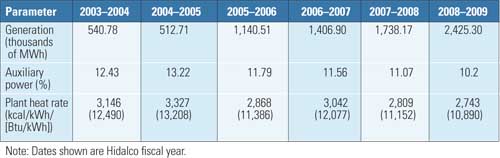
Cut your losses. Hirakud Power has almost quintupled production in the past five years while also significantly reducing plant auxiliary power losses. Source: Hirakud Power
Add Fluid Couplings to ID Fans. Units 2, 3, and 4 have six induced draft (ID) fans each (two per boiler for a total of 18), each rated at 480 kW. By regulating the speed of the fans with a fluid coupling, the power consumed by each motor was reduced by approximately 60 kW, thereby reducing annual energy usage by 9,460 MWh. The simple payback on this project was less than two years.
Add VFD to SA Fans. The nine newest CFB boilers also have a total of 18 secondary air (SA) fans, each rated at 180 kW and sized at 60% of the SA flow. The CFB boilers typically operate at 85% of maximum continuous rating. Instead of using inlet guide vanes to control flow at reduced load operations, variable frequency drives (VFD) were added to each 415-V motor. Each 180-kW motor saves 32 kW when operating, for a total annual energy savings of 5,050 MWh. The simple payback on this project was less than three years.
Add Fluid Couplings to Boiler Feed Pumps. Units 2, 3, and 4 have three boiler feedwater pumps each, each rated at 1,300 kW. Fluid couplings were added to each pump, which reduced auxiliary power by 268 kW per pump, resulting in an average annual energy savings of 14,090 MWh. The simple payback on this retrofit was less than one year.
Above Average
Hirakud Power continues to go beyond what is legally required by its plant operating permits to maintain a small environmental footprint. For example, the plant’s stack particulate emissions remain at about 25% below the permit limit of 80 mg/Nm3, and the staff have reduced fugitive dust emissions in the entire coal and ash lifecycle far below the local residential standard of 200 µg/m3 and close to the background air quality.
In addition, Hirakud Power was able to recycle more than 40% of the ash generated by the plant last year into beneficial uses, such as construction materials, including bricks and cement for the construction of roads and stormwater holding and protection dikes.
—Dr. Robert Peltier, PE is POWER’s editor-in-chief.