Thermocouple Response Time Study for Steam Temperature Control
One important factor in power plant control system performance is the response time of the process measurement used in the control system. The response time of boiler steam temperature sensors and thermowells is examined, as is those sensors’ and thermowells’ effect on desuperheater temperature response time and, therefore, steam temperature control performance.
Temperature measurements are used extensively in power plants to monitor and control many important processes. Some of the most critical temperature measurements are of steam temperatures in the boiler, in particular the final superheater outlet temperature and the desuperheater outlet temperature.
In a typical drum boiler, the dry saturated steam leaving the drum passes through multiple superheating sections before it leaves the boiler. A very common temperature control method is to inject water into the steam between superheater sections to cool the steam. The steam and water temperatures are commonly used in a cascade steam temperature control system in which the final temperature is the measured variable for the outer control loop and the desuperheater outlet temperature is the measured variable for the inner loop.
In any control loop, the response time of the process is an important factor in the performance of the loop. Faster-responding processes are generally easier to control tightly. Temperature measurements in steam boilers and many other processes have inherently slower response times than many pressure and flow measurements.
The total response time of the temperature measurement consists of the response time of several components in the temperature measurement system. When measuring temperature in high-pressure steam lines, the relatively fragile temperature sensors are installed in thermowells to protect the sensors from the harsh steam conditions. The thermowells are heavy metal tubes and, consequently, slow down the temperature response at the sensor.
Other factors in the overall temperature measurement response time include the heat transfer from the steam to the thermowell, conduction across the thermowell, heat transfer from the thermowell to the sensor sheath, and heat transfer to the sensor itself. If the sensor is not fully inserted in the bottom of the well, the heat transfer between the well and the sensor will be significantly degraded.
Making Superheated Steam
In a drum boiler, steam is generated in the furnace waterwall tubes, and the boiling steam/water mixture is returned to the drum. In the drum, the steam is separated from the water before leaving the drum on its way to the superheater. The superheater is arranged in multiple sections with the first section called the primary superheater. There may be one or two additional superheater sections, depending on the particular boiler’s design, as assumed in this discussion. Between the two sections of superheaters is a desuperheater in which water from the feedwater system is injected through spray nozzles into the steam for steam temperature control.
As the water evaporates, it cools the steam and provides a means of temperature control. Evaporation happens very quickly, provided the spray nozzles atomize the spray water well. The temperature just downstream of the desuperheater after evaporation is completed is measured and referred to as the desuperheater outlet temperature.
After the steam leaves the desuperheater, it passes through the final superheater before leaving the boiler. The temperature of the steam leaving the boiler is also measured and referred to as the final superheater outlet temperature. The flow of water into the desuperheater is regulated by a modulating control valve, which is supplied with feedwater from the boiler feedpump discharge or from the economizer inlet.
Time Response Characteristics
To begin, assume that the initiating event for the control system is a step change in the position demand to the spray valve. The valve position response for a pneumatic valve can be approximated by 1 to 2 seconds of dead time followed by a 2- to 5-second time constant (Figure 1). The water flow into the desuperheater responds almost instantly to changes in the spray valve position. The desuperheating process is a very quick process, so the actual steam temperature leaving the desuperheater changes almost as fast as the water flow entering the desuperheater. The time constant of the water flashing into steam probably is less than 1 second.
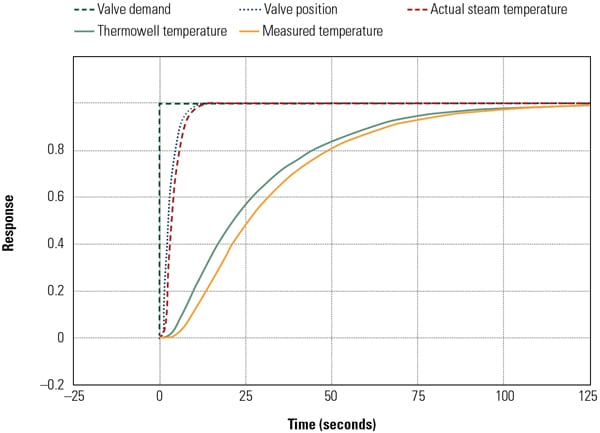 |
| 1. Great expectations. This diagram shows the expected time response of desuperheater components. Courtesy: Southern Company Generation |
The measured temperature of the desuperheater outlet responds considerably slower than the actual temperature. The response characteristic for the measured temperature should be approximately 2 to 3 seconds of dead time followed by a 30-second time constant based on tests conducted on several nearly new units in the 1980s. The 30-second time constant is based on the combined effects of the thermowell and the temperature sensor, with the thermowell being the dominant effect.
Also based on past unit testing, the response time of the final outlet temperature at the boiler is typically about 60 seconds of dead time followed by a 100- to 200-second time constant due primarily to the large metal mass of the superheater.
Plant Test Results
Several open-loop step response tests were conducted on the superheater spray valves on the unit under study, a 270-MW coal-fired drum unit. While the unit was at steady-state conditions, the spray valve demand on one side was stepped up by the operator. The unit was given approximately 20 minutes to come to a new steady-state condition. It was clear from the data that there were disturbances present and that these disturbances made it more difficult to measure the actual response times. The desuperheater outlet temperature response time was approximately 90 to 100 seconds (Figure 2), which was considerably slower than the expected response time of 30 seconds. This discrepancy between the expected and actual response time initiated an investigation into the cause.
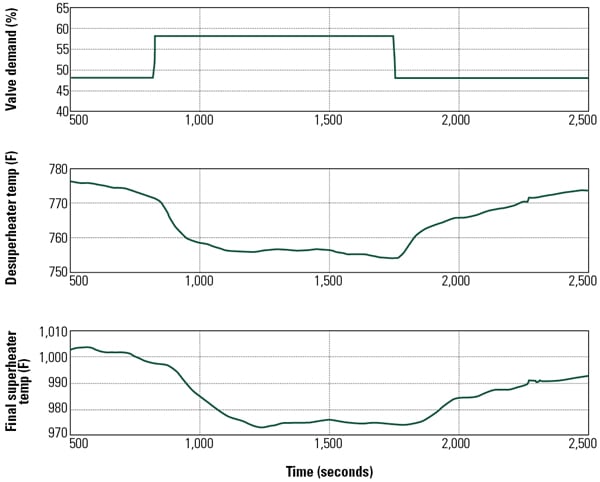 |
| 2. Disturbing results. Spray valve open-loop step response test results are shown. The desuperheater outlet temperature response time was approximately 90 to 100 seconds, which was considerably slower than the expected response time of 30 seconds. This discrepancy between the expected and actual response time initiated an investigation into the cause. Courtesy: Southern Company Generation |
Plant Findings on Thermocouple Installation
As a result of the slow time response observed on the desuperheater outlet thermocouple (TC), plant staff began checking the installation in an attempt to identify the cause. Several problems were found, including these:
- The TC spring-loading mechanism appeared to be insufficient, which may have allowed the TC tip to not be in direct contact with the bottom of the thermowell.
- The inside diameter of the thermowell was 0.5 inch and the outside diameter of the TC was 0.25 inch, so there was a considerable air gap around the outside of the TC.
- The TC was ungrounded, meaning that the TC junction was not directly touching the tip of the TC sheath. The thermal insulation within the sheath slows down the response of the TC.
- The thermowell design was very heavy duty and featured a straight shank rather than a tapered shank. The wall thickness of the straight shank was 0.437 inch throughout its length. The thickness of the bottom of the thermowell was not known but was thought to be approximately the same as the wall thickness.
- The TC tip design itself seemed to be not very conducive to quick response time, and the condition of the lead wire insulation inside the sheath was questionable and had some indications of electrical shorts between leads in the sheath.
To address these problems, plant staff installed new TCs in the left hand and right hand desuperheater outlet locations. The thermowell was not changed. The new TCs were grounded (Type K), 0.5 inch in diameter, and were installed with spring loading in the head to ensure that the TC remained in direct contact with the bottom of the well at all times.
After the new TCs were installed, the open-loop step response tests were repeated and, maybe surprisingly, the time constant of the temperature measurement did not noticeably change. The conclusion drawn from this discovery was that the main culprit in the slow response time was the heavy-duty, straight-shank thermowell.
Heat Transfer Analysis
To investigate this problem further, several finite element analysis (FEA) models of the existing and more common thermowells were developed to analyze the time response of the heat transfer from the fluid outside of the thermowell to the TC element. ANSYS Mechanical (an FEA platform from ANSYS Inc.) was used as the simulation environment for these studies. Effects included in this study were:
- TC design—exposed, grounded, and ungrounded TCs
- Thermowell design—straight-shank and tapered-shank designs
- TC sheath diameter and thermowell bore diameter
- Contact of TC tip to thermowell
- Convection heat transfer from fluid to thermowell
- Conduction heat transfer through thermowell
- Contact heat transfer from thermowell to TC sheath
- Convection heat transfer from thermowell to TC sheath (when there was a gap)
- Conduction heat transfer from the TC sheath through the TC insulation to the TC junction
Given this article’s space constraints, the three most significant of the many possible arrangements are discussed below.
Thermocouple Sheath/Thermowell Bore Diameter Mismatch. Among the many design choices for instrumentation and control designers are the selection of the TC sheath diameter and thermowell bore diameter. Common historical practice is for the TC diameter to match the thermowell bore diameter. For example, for a thermowell with a 0.385-inch diameter bore, a TC with a 0.375-inch (3/8th-inch) sheath diameter would be selected. This combination would provide a relatively large contact area between the TC and thermowell, greatly improving heat transfer characteristics. Conversely, a known adverse impact is that the relatively close fit would make the TC more difficult to replace. The impact of this mismatch for a 10F increase in steam temperature is shown in Figure 3.
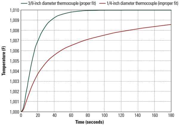 |
| 3. Irreconcilable differences. Common historical practice is for the thermocouple diameter to match the thermowell bore diameter. The impact on the response time of a thermocouple sheath/thermowell bore diameter mismatch is shown in this chart. Courtesy: Southern Company Generation |
As shown, the measurement time constant increases from approximately 19 seconds to 64 seconds. The following assumptions are relevant to these results: the 3/8-inch TC is in intimate contact with the thermowell throughout its length and the ¼-inch TC contacts the thermowell only at the base of the thermowell. Arguably, these two assumptions place the mismatch in the most adverse light, but the results are indicative of the large response time differences that can be obtained.
Thermowell Design. As discussed previously, the “robust” straight-shank thermowell design has significant adverse impacts on the desuperheater outlet response time. The relative impact for the exposed type of TCs is shown in Figure 4. As shown, the time constant for the straight-shank design is more than twice that of a more typical tapered design.
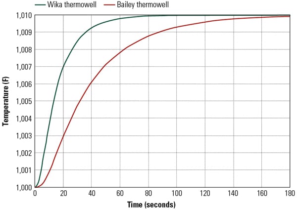 |
| 4. Just the right amount of exposure. The impact on response time of different thermowell designs using properly fitted exposed-tip thermocouples is shown. Courtesy: Southern Company Generation |
Thermocouple Not Properly Seated. As might be expected, if the TC is not seated properly, the response time will increase substantially. Analysis showed the time constant increasing by an order of magnitude (~30 seconds to ~300 seconds).
Lab Tests Verify Effects
Lab tests using precision thermowells and TCs were used to verify and refine the FEA results. Wika Instruments provided two threaded, tapered thermowells—one with a ¼-inch bore and one with a 3/8-inch bore. Wika also provided two sets of TCs—one set of ¼-inch diameter and one set of 3/8-inch diameter. Each set contained an exposed, grounded, and ungrounded TC.
Because testing would be extremely difficult to perform in the steam line of interest, the tests took place in a lab setting using a molten salt bath at 350F. A room temperature thermowell was submerged in the molten salt. An array of five grounded 1/8-inch TCs (chosen for their short response time) was submerged simultaneously. The responses of all TCs (including the one in the thermowell) were recorded. This test was performed for all thermowell and TC combinations—a total of nine test runs.
The results of these tests were compared with the results of a separate set of FEA models. These FEA models were created specifically to model the lab tests with initial conditions, bulk temperatures, and convection values adjusted to the conditions of each individual test. If necessary, the FEA models were to be adjusted until the FEA results and the lab results correlated closely.
Possible areas of refinement for the FEA models included the addition of contact resistance, the adjustment of convection values, and the addition of heat transfer to the base of the thermowell (or heat “leaving” the thermowell). It was found that none of these refinements was necessary. However, due to salt temporarily solidifying on the thermowell, it was necessary to model a dynamic load up to the point of when the salt melted off of the thermowell. Beyond this point, the FEA models were nearly identical to the lab results, and it was determined that the method of modeling and calculating a convection value was valid.
Because the thermowells have internal conditions that are nearly identical at low and high temperatures, these validated models were used to simulate the response at high-temperature steam conditions (with adjustments made for convection and other fluid conditions).
Impact on Control System Performance
It is known that adding a time lag in the feedback of a control loop will degrade the performance of the loop. In this study, it appears that the time lag of the desuperheater outlet temperature is actually about 100 seconds, when it was expected to be about 30 seconds. This measurement is used as the feedback signal for the inner loop of a typical cascaded steam temperature control strategy. To evaluate the impact that the additional time lag has on the overall loop performance, a simple dynamic model of the control system and the process was developed in the MATLAB/Simulink environment.
The control system was equivalently tuned for two different desuperheater outlet temperature measurement response times, 25 seconds and 100 seconds. The final superheater temperature measurement response model was the same for both cases. Transients were performed on both the fast and slow models to quantify the impact of the change in the inner loop process response on the control performance. The transients consisted of four step changes in setpoints and disturbances. Throughout the transient analysis, the control performance of the faster-responding loop is better than that of the slower-responding loop (Figure 5), as expected.
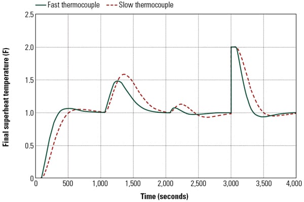 |
| 5. On the fast track. The comparison of control performance with fast and slow inner loop temperature measurement is shown. Courtesy: Southern Company Generation |
Many factors influence the overall response time of temperature measurement in boiler steam lines. In this project, the response time of one common boiler temperature measurement, taken at the desuperheater outlet, found that a thick-walled thermowell was the primary culprit in the longer-than-expected response time.
In fact, the thick-walled design resulted in almost double the time constant of a more typical tapered tip design. Laboratory tests to verify the FEA models were performed and confirmed these results. Further tuning to allow for the thermodynamic lag caused by the thermowell improved the responsiveness of the plant controls.
This article is based on a paper presented by the authors at the 15th Annual POWID/EPRI Controls and Instrumentation Symposium.
— Cyrus Taft ([email protected]) works for Taft Engineering Inc. in Harriman, Tenn. John Sorge ([email protected]) works for Southern Company Generation in Birmingham, Ala. Jackson Willis (jackson@ roycmartin.com) is a sales engineer for Roy C. Martin & Co.