Thermocouple Response Time Study for Steam Temperature Control, Part II
Mismatched or poorly maintained temperature sensors and thermowells can cause an often-unrecognized error in steam temperature measurement. The problem is often recognized only when sluggish steam temperature response times are noticed. Recent tests suggest some simple ways to resolve the problem.
Sensor response time is an important factor in control loop performance. In general, faster-responding sensors lead to better control loop performance.
For steam temperature control in a fossil-fired steam power plant, two temperature measurements are commonly used: one at the desuperheater outlet and the other at the final superheater outlet. Typically, a cascade control strategy is utilized for this application, and the desuperheater outlet temperature is the process variable for the inner loop and the final outlet temperature is the process variable for the outer loop.
Because the dynamics of the spray-type desuperheater are quite fast, the temperature measurement response time at that location should be similarly fast, if possible. At the plant where the study discussed below was done, initial testing showed the desuperheater temperature response time to be approximately 70 to 80 seconds, which is much longer than the roughly 30 seconds that the authors expected. A study was conducted to investigate the cause of the longer response time, and the conclusion was that the thermowell design was overly robust, which caused excessive heat transfer delay between the steam and the thermocouple element. (See “Thermocouple Response Time Study for Steam Temperature Control” in the February 2011 issue of POWER, available in our archives at https://www.powermag.com.) Plans were made to replace the thermowell with a more modern, tapered design, and finite element analysis showed that the response time would be significantly reduced.
The thermowell was replaced in 2011, and testing was done to quantify the new response time. In addition, the old thermowell was found to have considerable debris inside when it was removed and inspected. Laboratory temperature response tests were done in the as-found condition and also after the bore was cleaned, in an attempt to determine what effect the debris had had on the initial response time.
Thermowell Removal and Replacement
The desuperheaters are located in the boiler penthouse, which is an enclosed area just above the top of the furnace. That location can only be accessed during a unit outage lasting several days. Removal of the old thermowell and installation of the new one was delayed for many months at this plant until a scheduled outage was begun. The old well had been threaded into the pipe downstream of the spray injection point and seal-welded to prevent leaks. Once the seal weld was removed, the thermowell was unscrewed from the pipe. Then the new thermowell was screwed into the pipe and seal-welded.
The old and new thermowells are shown in Figure 1, where the difference in tip diameter is clear. The old thermowell had a straight shank with a bore diameter of 0.5 inch and a wall thickness of 0.468 inch, which makes the tip diameter 1.437 inches. The new thermowell has a bore of 0.26 inch and a tip diameter of 0.75 inch. A smaller tip diameter is the main factor in decreasing the response time of the new thermowell.
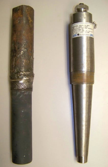 |
| 1. Side by side. Old and new thermowells show the clear difference in tip diameter, the main factor in decreasing the response time of the new thermowell. Source: Southern Company |
Response Testing
After the new thermowells were installed and the unit was back online, open-loop step response tests were performed on the superheater spray valves. These tests were done by placing the steam temperature controls in manual mode and manually moving the spray valve quickly from one position to another. The desuperheater outlet temperature was recorded and analyzed to determine the response characteristics, in this case three parameters: gain, time constant, and dead time.
For the first test shown in Figure 2, the time constant was 17.4 seconds and the dead time was 9.8 seconds. For the second test, the time constant was 20.2 seconds and the dead time was 9.8 seconds. These tests were done at approximately 100 MW. The times represent the response from the valve position demand signal to the measured temperature, so the response of the valve actuator is included in this response time. A similar test on the old thermowell produced a time constant of approximately 70 seconds, so there was a dramatic reduction with the new thermowell. Other tests with the new thermowell were done at 270 MW, full load, and the time constant for those tests averaged 16 seconds with an average dead time of 3.8 seconds.
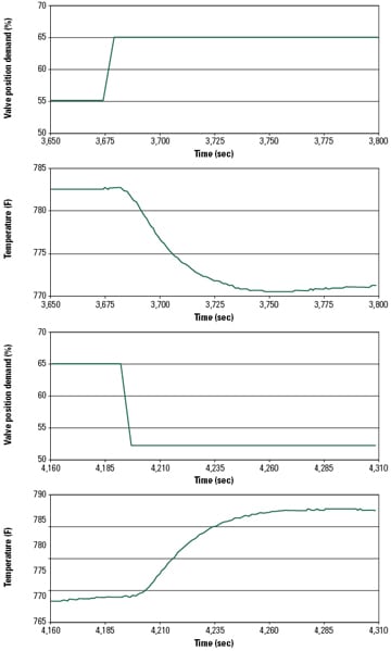 |
| 2. Test responses. Step responses of desuperheater outlet temperature to a change in spray valve position are shown. The response to a step change open is shown in the top two graphs, and a step change close is shown in the bottom two. Source: Southern Company |
Impact on Control Loop Performance
The February 2011 article on this topic explained how a simple simulation was done to evaluate the effect of a faster temperature response on the performance of a cascade proportional integral derivative (PID)–based steam temperature control loop. That simulation showed that there was a significant (but not huge) improvement in the disturbance rejection capability of the controls with a faster temperature measurement.
As a result of another research project on the steam temperature control, a model predictive controller was in service during the time the thermowell was replaced, and that controller did not utilize the desuperheater outlet temperature. This made it impractical to try to assess the impact that the faster response had on the control system performance. Recently, a modified PID-based control strategy was installed for testing that does use the desuperheater outlet temperature, so it may be possible with this system to make a control performance comparison between the fast and slow temperature measurement responses.
After the old thermowells were removed, the bores of the wells were inspected using a small borescope. Considerable debris was found in the bore of one thermowell, and some of it appeared to be metallic (Figure 3). Some of this debris may have fallen into the thermowell when the thermocouple was removed during removal of the thermowell. This discovery required determining the nature of the debris and what impact it might have had on the slow response time observed with the old thermowell.
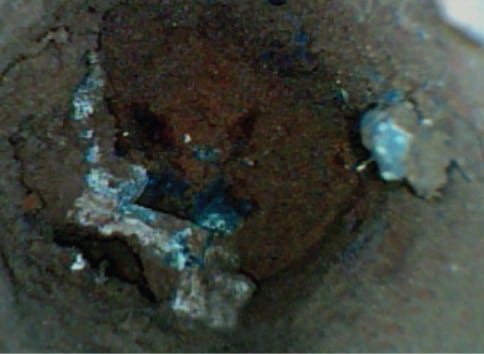 |
| 3. Bore debris. This debris was found in the bottom of a bore in one of the old (removed) thermowells. Courtesy: Southern Company |
A plan was developed to test the old thermowell using the same temperature calibration facility described in the earlier article. Tests were to be conducted first in the as-found condition and later with the bore cleared of all debris. Unfortunately, the thermowell with the most debris was too badly damaged during removal to be tested in the lab, so the thermowell with less debris was tested.
Because tests would be extremely difficult to perform in the steam line of interest, they were conducted in a lab setting with a molten salt bath at 350F (Figure 4). For each test, a room temperature thermowell was submerged in the molten salt and the temperature response was recorded. The most recent test focused on assessing the performance of the nontapered thermowell and on repeating a subset of the first round of tests to confirm previous results (Table 1).
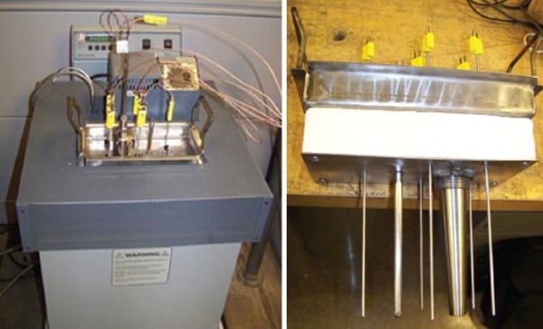 |
| 4. Molten salt test. Field-testing was impractical, so a laboratory setting with a molten salt bath at 350F was used to assess performance of the nontapered thermowell and to confirm earlier test results. The Hart Scientific heat bath with thermocouple tray used for testing thermocouple response times (L) and the underside of the tray holding test thermowell and reference thermocouples (R) are shown. Source: Southern Company |
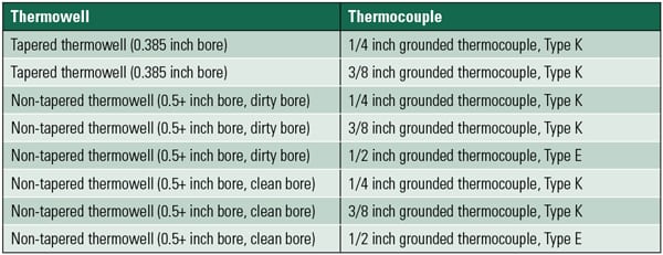 |
| Table 1. Tests conducted in the thermal bath in the second round of testing. Source: Southern Company |
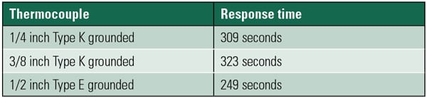
The “submersion test” results for the nontapered, dirty-bore thermowell are shown in Figure 5. For these three tests, the response times (time to reach 63% of the final value) were approximately those shown in Table 2.
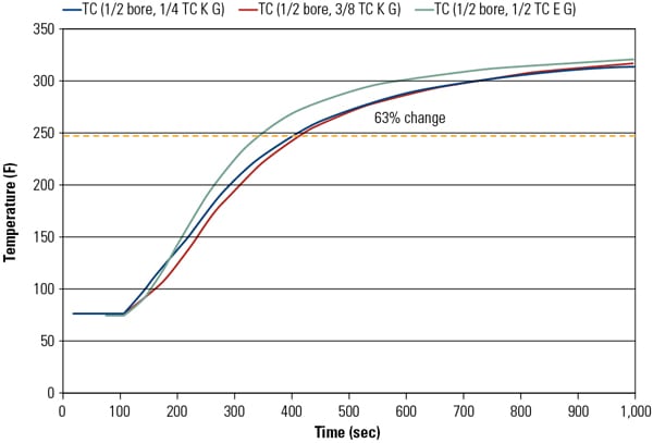 |
| 5. Submersion test results. The results of a submersion test for a straight shank, dirty-bore thermowell with various size thermocouples is illustrated. The system response is the time required to reach 63% fo the final value. Response curves for each of the tests described in Table 1 were developed. Source: Southern Company |
 |
| 5. Submersion test results. The results of a submersion test for a straight shank, dirty-bore thermowell with various size thermocouples is illustrated. The system response is the time required to reach 63% of the final value. Response curves for each of the tests described in Table 1 were developed. Source: Southern Company |
As expected, the response was faster for the ½ inch thermocouple than the other two (1/4 inch and 3/8 inch), which confirms the need to match thermocouple diameter to thermowell bore diameter to obtain the fastest response time. Of course, these results were conducted in a salt bath and not steam conditions. For that application, the thermowell outside surface convective heat transfer coefficient is approximately three times that observed in the salt bath. When this increase in heat transfer coefficient is considered, the projected response time in the steam line is approximately 75 seconds and compares very favorably to the 70 seconds observed during plant testing.
Next, the bore of the nontapered thermowell was cleaned and the submersion tests were repeated. For these three tests, the response times (time to reach 63% of the final value) were approximately those shown in Table 3.
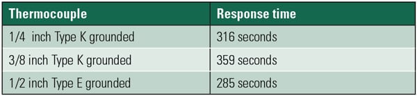 |
| Table 3. Submersion test results after the nontapered thermowell bore was cleaned. Source: Southern Company |
Note that the response times for the cleaned bore are greater than for the dirty bore (Figures 4 and 5). This result is counterintuitive but may be due to surface imperfections with the dirty bore that created greater contact area between the thermowell and the thermocouples, thus improving that heat transfer coefficient, or to unknown and uncontrolled factors in the test method.
As shown, cleaning the thermowell had very little impact on the response time of the 1/4-inch thermocouple, likely because the response time of this thermocouple is largely driven by the relatively small point of contact area between the thermowell and thermocouple (arguably, just at the tip). For the 1/2-inch thermocouple, the response time with the dirty bore was slightly faster (by approximately 15%) than that observed with the clean bore. Again, this may be attributable to greater surface contact area provided by the dirty bore.
One important factor in control system performance is the response time of the process measurements used in the control system. In this article, the response time of one common boiler temperature measurement, the desuperheater outlet, is examined. Step response tests on an actual unit produced unexpectedly long response times, which prompted further investigation to identify the cause. Several issues related to installation of the thermocouple were identified, but replacing the thermocouple and correcting the installation issues did not improve the response time. The only component not replaced was the thermowell, which was a particularly thick-walled design featuring a nontapered shank. These thick-walled thermowells were replaced with tapered designs during the third quarter of 2011, and this replacement resulted in a much faster closed-loop response time for the desuperheater outlet temperature control loop.
One of the original straight-shank thermowells was response tested in a laboratory, and the preliminary results confirm the response time measured in the plant. Having a fast response time for this loop is important for improving final steam temperature control for units that utilize a cascade control scheme.
Though many factors influence the overall response time of temperature measurement in boiler steam lines, in this particular case, the thick-walled thermowell was the primary culprit for a slow response.
— Blake Feltman ([email protected]) and John Sorge, PE ([email protected]) work for Southern Company Generation in Birmingham, Ala. Cyrus Taft, PE (cwtaft@ taftengineering.com) works for Taft Engineering Inc. in Harriman, Tenn. This article is based on a paper presented by the authors at the 2012 ISA POWID Symposium.