The Role of Fireside Corrosion on Boiler Tube Failures, Part II
One of the primary challenges of reliably burning coal is managing the corrosion experienced by the furnace heat transfer surfaces. Fireside corrosion remains a leading cause of failure in superheater and reheater tubes. Tubes affected by fireside corrosion also may lose 15 mils per year (mpy), or more in extreme cases. In Part I of this two-part report, three case studies examined the different failure modes experienced by tubes located throughout the furnace. We conclude with two additional case studies.
Case 4: Ash Corrosion of a Superheater
An intermediate superheater tube was received for failure analysis. The tube had been removed from the outlet and below the middle sootblower. The tube was specified as 2.125-inch outside diameter (OD) x 0.290 inch MWT SA-213 T11 Cr-Mo steel. It had been in service for one year. Agricultural waste was burned.
Figure 1 shows the as-received tube with specimen locations illustrated, including a close-up of the failure site and the tube inside diameter (ID) view. The failure was thick-edged and fish-mouthed, characteristics of creep failure. A shield had been installed recently on the tube to protect it from erosion/fireside corrosion. The failure had occurred slightly below the shield. Significant wall thinning was observed on the side facing into the gas flow. The tube suffered from significant fireside corrosion on the side where the failure had occurred.
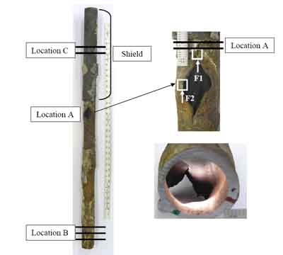
1. As-received tube with specimen locations illustrated, including close-up of the failure site and the inside diameter (ID) view. Courtesy: David N. French Metallurgists
Very thick scale was observed on the OD, as shown in Figure 2. The severity of the fireside corrosion was revealed by the orange peel texture on the tube. A significant amount of chlorine was detected in the OD deposit. The chloride anions may have been formed during cathodic reaction of chlorine. The presence of chloride led to the formation of the low-melting species on the tube surface that contained iron, aluminum, and sodium chlorides. These chloride species would be expected to have a low melting point and would dissolve the protective iron oxide, leaving the bare steel to be corroded by hydrogen chloride.

2. Tube outside diameter (OD) with thick scale. Courtesy: David N. French Metallurgists
Elemental analysis was performed on deposit scraped from the OD surface. Analysis was via energy dispersive spectroscopy in the scanning electron microscope (ASTM E1508-98 [2003]). The carbon and sulfur content was determined by combustion analysis (ASTM E1019-03). The results are summarized in Table 1.
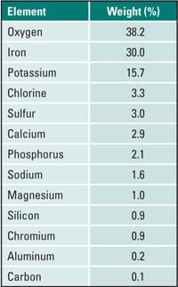
Table 1. Outside diameter deposit. Source: David N. French Metallurgists
The OD deposit was primarily iron oxide. A high percentage of chlorine indicates the formation of the low-melting liquids that may have contained iron chlorides. The low-melting iron chloride would dissolve the protective iron oxide and expose the bare steel to the corrosive environment. Magnesium and aluminum were present from the ash deposits. Chromium was likely from the steel. The presence of carbon within the ash deposits indicates that the reducing conditions were present at least at the surface of the tube where corrosion occurred. With reducing conditions, iron-sulfide scales form rather than iron oxide. These iron-sulfide scales are less corrosion-resistant than oxides.
Figure 3 illustrates the failure at location F2, with the arrow indicating the fracture face. The wall thickness at the fracture lip was measured as 84 mils. This wall thinning rate was 206 mils per year. There was no significant plastic deformation at the edge of the failure. The tube failed due to significant wall thinning, resulting in creep. Creep cusps were found where the wall was thinnest. Creep had occurred from the tube OD to ID. Creep cusps formed on the tube OD because of the high-temperature exposure on the OD (Figure 4). Numerous creep voids were observed adjacent to the creep cusp and along the fracture face.
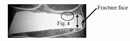
3. Location F2, 84 mils thick at 7x magnification. Courtesy: David N. French Metallurgists

4. Location F2, creep voids, OD, 200x magnification. Courtesy: David N. French Metallurgists
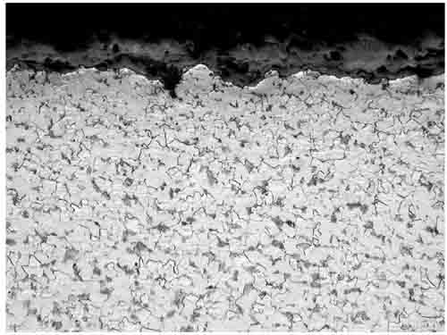
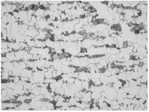
The microstructure in Figure 5 was ferrite with slightly spheroidized carbides, as expected for T11. Still, the original pearlite colonies were clearly defined. Thus, there was no evidence of localized overheating at the failure site. Similar microstructure was observed irrespective of the specimen location. Intergranular attack was observed on the OD due to the lack of protective oxide scale resulting from the fireside corrosion, as shown in Figure 6.
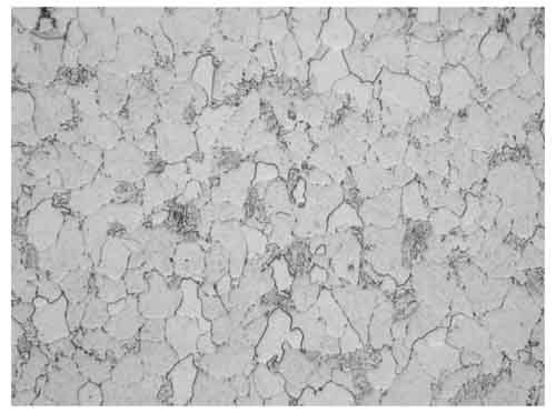
5. Location B, mid-wall, 12:00, 400x magnification. Courtesy: David N. French Metallurgists

6. Location B, intergranular attack, OD, 12:00, 200x magnification. Courtesy: David N. French Metallurgists
Ring samples (Figure 7) were sectioned from the tube for dimensional and hardness measurements (Table 2). Circles on the rings indicate thin spots. Significant wall thinning was observed, caused by fireside corrosion. The thinnest section of Ring A (0.120 inch at the 1:00 position) was at 41% of minimum wall thickness (MWT), Ring B (0.179 inch at the 11:00 position) was at 62% of MWT, and Ring C (0.145 inch at the 10:00 position) was at 50% of MWT. If the tube had thinned below 65% of MWT, the first choice should be tube replacement. Careful inspection via ultrasonic thickness measurement was recommended, with replacement of tubes less than 0.190-inch thickness. The hardness, averaging 78 Rockwell B (RB) was within the range for new tubing specification SA-213 T11, 76 to 85 RB, indicating that no overheating or metallurgical transformation had occurred.
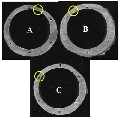
7. Sectioned rings. Courtesy: David N. French Metallurgists
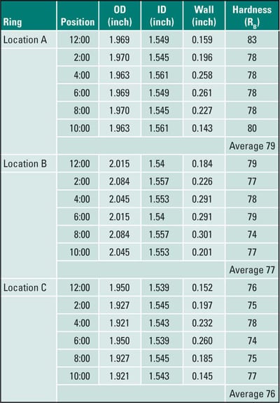
Table 2. Case 4 dimensional and hardness measurements. Source: David N. French Metallurgists
The tube failed due to significant wall thinning caused by fireside corrosion, resulting in creep. Reducing conditions led to the formation of porous iron sulfides rather than iron oxides. Hydrogen chloride had easily attacked iron sulfides to form iron chloride as a corrosion product. These iron chlorides had a relatively low boiling point, and therefore iron chloride vapors formed, and the corrosion mechanism was by loss of iron as a vapor. The porous sulfides formed due to reducing conditions allowed easier formation and removal of iron chloride vapor. Significant wall thinning was observed. The microstructure was ferrite with slightly spheroidized carbides, as expected for T11.
Case 5: Fireside Corrosion of a Waterwall Tube
A rear wall tube was received for condition assessment. The tube was specified as 2.97-inch OD x 0.240-inch MWT, SA-210 A1 carbon steel. It had been in service for only nine months. Figure 8 illustrates the ID view, which shows a uniform oxide covering. The tube appears to be very clean inside. Figure 9 shows the tiny pits observed on the fireside OD surface. The surface deposits had been removed with diluted hydrochloric acid containing a corrosion inhibitor to reveal the underlying steel. These pits were observed between the 12:00 and 2:00 orientations of the tube.
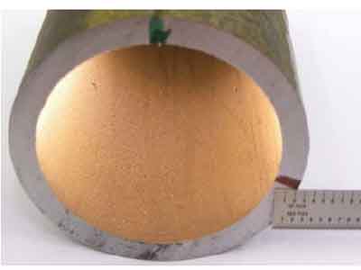
8. Tube ID view. Courtesy: David N. French Metallurgists

9. Pits on the fireside OD surface. The green line marked the crown of the hot side of the tube. Magnification is 2.5x. Courtesy: David N. French Metallurgists
Some intergranular attack was seen at the OD (Figure 10). This attack was a cross-section of a longitudinal line of attack on the surface of the tube. Another linear indication, at the 11:00 orientation, was cross-sectioned and found to be 4 mils deep. Typical microstructure was observed with ferrite and pearlite in Figure 11, without any thermal degradation. Similar microstructure was observed on the other side of the tube.
10. The fireside showed intergranular attack: OD, 200x magnification. Courtesy: David N. French Metallurgists
11. Ferrite and pearlite microstructure, fireside, mid-wall, 400x magnification. Courtesy: David N. French Metallurgists
A ring sample (Figure 12) was sectioned from the tube for dimensional and hardness measurements (Table 3). The tube had not bulged. Taking the difference between the thickest and thinnest sections, the wall thinning was measured as 11 mils. This wall thinning is significant for waterwall tube about nine months old and is a wastage rate of about 15 mils/year. None of the measured wall thickness values was below MWT of 0.240 inch. The wall thinning resulted from the fireside corrosion on the OD. The hardness, averaging 73 RB is within the range for new SA-210 A1, 72 to 78 RB, indicating that no overheating or metallurgical transformation had occurred.

12. Sectioned ring. Courtesy: David N. French Metallurgists
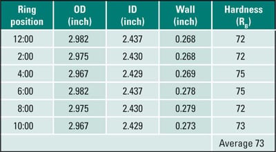
Table 3. Case 5 dimensional and hardness measurements. Source: David N. French Metallurgists
Elemental analysis was performed on deposit scraped from the OD surface. Table 4 shows that the deposit was primarily iron oxide. The presence of carbon within the ash deposits indicates that reducing conditions were present. The lead content was very high, and its melting point is 620F. This may be a significant factor in the tube wastage. The presence of chlorine content indicates the formation of the low-melting liquids that contained lead, zinc, and iron chlorides. Elemental results also suggest that K2S2O7 may have been involved in the fireside corrosion. K2S2O7 and Na2S2O7 are the primary susceptible compounds for fireside corrosion on waterwall tubes. The melting points of K2S2O7 and Na2S2O7 are 750F and 570F, respectively. Mixtures of these two compounds could melt at even lower temperature.

Table 4. Case 5: OD deposit. Source: David N. French Metallurgists
Scanning electron microscope (SEM) images were taken at high magnification on the OD of the cleaned tube sample. In Figures 13 and 13, SEM images revealed a linear indication on the cleaned tube sample, indicating some fireside corrosion. Inhibited acid was used for cleaning. This is a view from the surface of a longitudinal line of intergranular corrosion like that shown in cross-section in Figure 10. The corrosion may have followed a line of nonmetallic inclusions in the steel or a die mark.
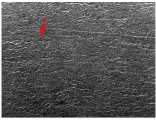
13. Scanning electron microscope (SEM) image (30x magnification) of the tube OD. The linear indication is shown by the arrow. Courtesy: David N. French Metallurgists
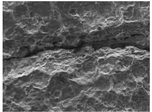
14. SEM image of the tube OD with a close-up of the linear indication at 645x magnification. Courtesy: David N. French Metallurgists
Hemispherical-shaped surface pits were observed on the cleaned sample. At high magnification (Figure 15), some intergranular attack could be seen inside these hemispherical pits. This attack at the grain boundaries is due to lack of protective scale there. The scale was apparently removed in service, perhaps by a molten or semi-molten phase.
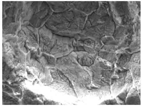
15. SEM image of the tube OD with a close-up of the linear indication at 1,810x magnification. Shown is intergranular attack inside a pit. Courtesy: David N. French Metallurgists
The tube suffered wall thinning resulting from fireside corrosion at a rate of 15 mils/year. This is a high rate of corrosion, though none of the measured wall thickness values was below the MWT of 0.240 inch. Reducing conditions in the furnace may have contributed to the OD corrosion. The formation of low-melting species on the tube OD may also have led to rapid corrosion. Chloride and sulfide species had dissolved the protective iron oxide, exposing bare steel to the corrosive environment, resulting in significant wall loss. Potassium pyrosulfate may have formed in the OD deposit and contributed to wall loss. The presence of lead and zinc may have further reduced the melting points of OD deposit. Typical carbon steel microstructure, with ferrite and pearlite, was observed without any degradation.
Controlling Fireside Corrosion
Irrespective of the boiler type, fireside corrosion affected the superheater/reheater tubes, resulting in significant wall loss. As demonstrated, waterwall tubes are also susceptible to fireside corrosion. Different methods have been proposed for controlling fireside corrosion, including reducing sulfur content, installing shields, adding additives, and applying corrosion-resistant weld overlays. Following are a few observations about potential options for minimizing fireside corrosion:
- Coal ash corrosion rates drop drastically above 1,250F due to decomposition of complex alkali trisulfates. Shields decrease heat transfer from the flue gas to the steam, resulting in increase of the tube outside temperature above the range of stability of complex trisulfates. To cause oil ash corrosion, impurities in the fuel oil (Na, V, and Pb) along with sulfur must be present. Oil ash corrosion can be minimized by reducing impurities in the fuel and by desulfurization of fuel oil. Unfortunately, desulfurization of fuel oil is not an economical solution. Shields are also an ineffective method of controlling oil ash corrosion, because low-melting species do not thermally decompose, unlike in coal ash corrosion.
- Additives, such as calcium and magnesium, may be helpful to increase the melting point of compounds that are formed on the tubes. The increased melting temperature would be higher than superheater/reheater operating temperatures.
- Maintaining oxidizing conditions inside the furnace potentially eliminates the formation of porous iron sulfide scales instead of protective iron oxides.
- Inaccurate burner angles may result in localized reducing conditions. Therefore, burners should be adjusted per design to have the correct stoichiometric mixture.
- Installation of low-NOx burners in coal-fired boilers has resulted in accelerated waterwall wastage. These low-NOx burners are expected to produce more H2S, instead of SO2 or SO3, in the combustion gas that promotes increase in the corrosion rates.
- Weld overlays of more corrosion-resistant alloys like Alloys 625 and 622 have been proven to be a long-term solution for fireside corrosion. The superior corrosion resistance of these superalloys in both oxidizing and reducing environments containing mixtures of acids has been attributed to the formation of Cr-rich oxides (Cr2O3).
—Dr. Rama S. Koripelli is metallurgical engineer, Dr. David C. Crowe is technical director, Dr. David N. French is founder, and Jonathan Brand is a senior metallurgical technician for David N. French Metallurgists.