The Role of Fireside Corrosion on Boiler Tube Failures, Part I
Normal
0
0
1
2808
16009
133
32
19660
11.0
0
0
0
One of the primary challenges of reliably burning coal is managing the corrosion experienced by the furnace heat transfer surfaces. Fireside corrosion remains a leading cause of failure in superheater and reheater tubes. Also, tubes affected by the fireside corrosion mechanism may lose 15 mils per year (mpy) and more in extreme cases. Five case studies (three presented here in Part 1) examine the different failure modes experienced by tubes located throughout the furnace.
Furnace Corrosion Fundamentals
Fireside corrosion in the superheaters and reheaters of coal-fired units is known as coal ash corrosion, in oil-fired units as oil ash corrosion, and in refuse-fired boilers as ash corrosion. Sometimes, fireside corrosion is also referred to as hot corrosion. The mechanism in each case is similar, but the low-melting species in each is different. In coal ash corrosion, the low-melting species would be sodium or potassium iron trisulphates (Na3Fe(SO4)3 or K3Fe(SO4)3); in oil ash corrosion they would be V2O5-Na2O or V2O5-Na2SO4; and in refuse-fired boilers they would be chlorides of iron and zinc along with other possibilities [see references 1 and 2 in the sidebar]. High temperatures (above 1,000F) of the superheater/reheater favor the formation of these low-melting compounds.
The corrosion rate in coal ash corrosion, between 1,100F and 1,250F, is very high. In this temperature range, Na2SO4/K2SO4 reacts with surface oxides in the presence of SO3 to form complex liquid sulfates (Na3Fe(SO4)3 or K3Fe(SO4)3) that result in rapid corrosion [3, 4]. Above 1,250F the corrosion rate is decreased significantly due to decomposition of these complex liquid trisulfates. Once the liquid phase has been removed, the corrosion is due to oxidation in contact with flue gas.
The corrosion constituents in oil ash corrosion are vanadium, sodium, potassium, and sulfur. The combustion of fuel oil may produce low-melting species V2O5-Na2O, V2O5-K2O, V2O5-Na2SO4, and V2O5-K2SO4. The melting points of these compounds range between 1,000F and 1,550F, depending on composition [4, 5, 6]. The oil ash corrosion mechanism is similar to coal ash corrosion: a low-melting-point liquid forms and it dissolves the protective iron oxides.
In refuse-fired boilers, chloride and sulfate species lead to the formation of low-melting- point liquids on the tube surface that may contain iron, zinc, lead, and sodium. These species dissolve the protective iron oxide and expose the bare steel to the corrosive environment, resulting in significant wall loss [7]. Reducing conditions inside the furnace may lead to the formation of iron sulfide instead of iron oxide. The presence of carbon and iron sulfide within the ash deposits indicates the presence of reducing conditions. Hydrogen chloride can more easily attack iron sulfides, rather than oxides, to form iron chloride as a corrosion product. This iron chloride has a relatively low boiling point, and therefore iron chloride vapors form in the superheater/reheater temperature range, and the corrosion mechanism is by loss of iron as a vapor. The porous sulfide formed in reducing conditions allows easier formation and removal of iron chloride vapor.
Furnace wall tubes are also subject to fireside corrosion, but the low-melting species differ from superheater/reheaters. Sodium and potassium pyrosulfate (Na2S2O7 or K2S2O7) have been responsible for furnace wall corrosion [1]. Both of these species melt below 800F, where the furnace wall tubes operate. The melting points of Na2S2O7 and K2S2O7 are 750F and 570F, respectively [4, 8, 9]. Mixtures of these two compounds could melt at even lower temperature. Melting points as low as 635F to 770F have been measured.
Case Study 1: Coal Ash Corrosion of a Superheater
One finishing superheater tube sample, from a coal-fired unit, was received for metallurgical analysis. The tube was specified as 1.875-inch outer diameter (OD) x 0.330-inch medium wall tubing (MWT), SA-213 T22 Cr-Mo steel. It had been in service for 23 years. Figure 1 illustrates the as-received tube sample and the inner diameter (ID) view. Significant wall thinning was observed on the flanks of the tube, characteristic of coal ash corrosion. Very hard scale was observed on the tube OD. On the steam side, there was a thick oxide.
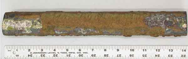
1. As-received tube and view of ID. Courtesy: David N. French Metallurgists
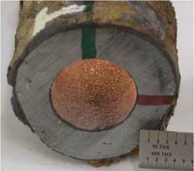
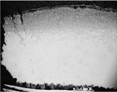
The tube sample was cross-sectioned, mounted, polished, and etched for metallographic examination. A 3% nital etchant (100 ml ethanol and 3 ml HNO3) was used to reveal the existing microstructure. Metallographic examinations were conducted via optical microscopy. Figure 2 shows thick scales at the tube OD and ID. A thick ID scale can raise the tube wall operating temperature significantly. Figure 3 is a view of coal ash corrosion that had occurred on the OD.

2. Cross-section of the tube wall facing the gas flow at 4.5x magnification. (Note that numbers on the images do not necessarily correspond to the numbering in this article.) Courtesy: David N. French Metallurgists
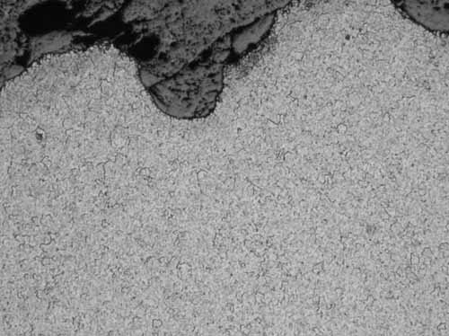
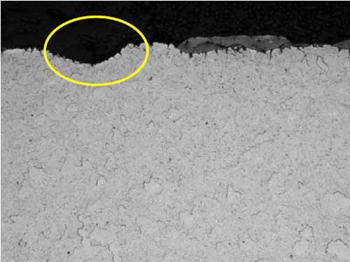
3. View of coal ash corrosion at 100x magnification. Courtesy: David N. French Metallurgists
As shown in Figure 4, the microstructure of the T22 tube had transformed to ferrite with spheroidized carbides. Metallographic examination was also performed at the 8:00 orientation of the tube to look for creep damage, if any. The microstructure was the same, irrespective of the specimen location, and there was no evidence of creep.
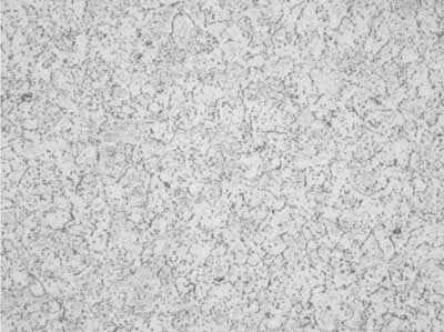
4. Ferrite with spheroidized carbides, mid-wall at 400x magnification. Courtesy: David N. French Metallurgists
Tube wastage will often be evident and manifested as flat spots on either sides of the upstream of flue gas flow, as can be seen in Figure 5a. A ring sample, Figure 5b, was sectioned from the tube for dimensional and hardness measurements (Table 1). The tube had thinned significantly at the 4:00 and 8:00 positions due to coal ash corrosion. The thinnest section of the ring (0.291 inch at the 8:00 position) was at 88% of MWT. The hardness, averaging 73 Rockwell B (RB), showed that the tube had softened after 23 years of service.
5a.
5b.
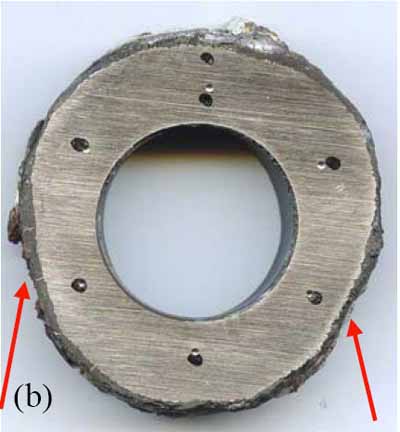
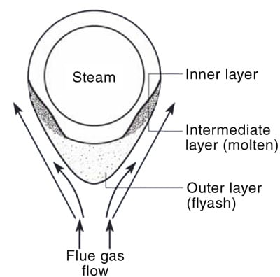
5. (a) Schematic representation of fireside corrosion. (b) Sectioned ring from the tube with corroded areas noted. The dark spots are the locations of hardness measurements. Courtesy: David N. French Metallurgists
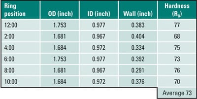
Table 1. Case 1 dimensional and hardness measurements. Source: David N. French Metallurgists
Alkali oxides react with SO3 in the furnace atmosphere to form alkali sulfates (K2SO4 or Na2SO4) on the oxide scale. Some of the SO3 diffuses through the alkali sulfates, and reaction occurs at the oxide-sulfate interface to form alkali-iron-trisulfates (K3Fe(SO4)3 or Na3Fe(SO4)3) according to the following two chemical reactions:
![]()
In this process, the thickness of the oxide scale decreases and the metal oxidizes further to renew the oxide layer. The tube metal temperature decreases as slag thickens. At room temperature, low-melting compounds sinter the ash particles to form a tightly bound inner layer. After the slag thickness reaches equilibrium, deslagging increases because the liquid layer on the tube cannot support a thick layer of ash. This deslagging increases the tube-metal temperature. This process (slagging and deslagging) repeats in a cycle that leads to create the corrosion pattern known as "elephant hiding" or "alligator hiding."
Coal ash corrosion of the tube analyzed in Case 1 resulted in significant wall loss. The temperature range for formation of trisulfates is between 1,000F and 1,250F. The decomposition of trisulfates occurs when the temperature exceeds 1,250F. Above this temperature, coal ash corrosion reduces significantly. Numerous empirical equations have been proposed for estimating the tube operating temperature based on the oxide scale thickness in superheaters and reheaters. Using one of these equation with the measured ID scale thickness (25 mils) and hours of operation (171,300 hours) results in an estimated tube temperature of 1,100F [11]. This estimated tube temperature was within the susceptible temperature range for trisulfate formation and coal ash corrosion. The metallography confirmed that the tube had operated in this temperature range. The tube microstructure had transformed to ferrite with completely dispersed carbides, and the hardness had decreased.
Log X = 0.00022 (T+460) (20+Log(t)) -7.25
Where:
X = steam-side scale thickness in mils
T = absolute temperature (F+460), and
t = time in hours
Case 2: Oil Ash Corrosion of a Reheater Tube
A high-temperature vertical reheater tube was received for failure analysis. The tube was specified as 2.25-inch OD x 0.180-inch MWT, SA-213 TP-304H stainless steel. It had been in service for 15 years. The fuel type was No. 6 Bunker C oil. Figure 6 is the as-received tube with specimen locations illustrated, including a close-up view at the failure site and the ID view. Significant wall thinning was observed at the failure.
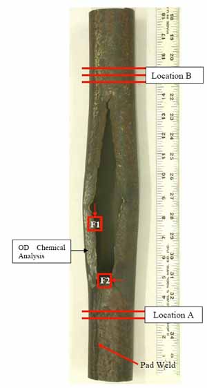

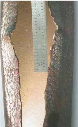
6. As-received tube with specimen locations illustrated, close-up of failure, and the ID view. Courtesy: David N. French Metallurgists
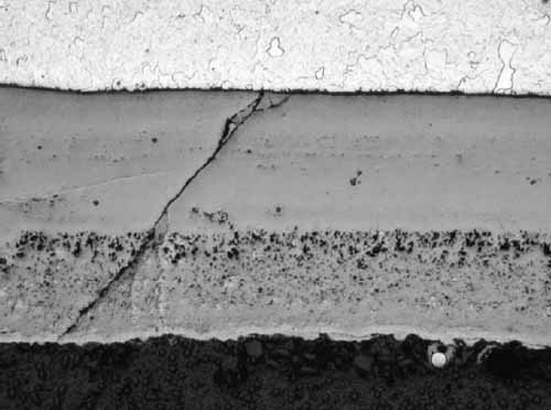
Figure 7 is a specimen at Location F1 with fracture face on the left. The tube is darker in the outer one-third of its cross-section due to carburization. Intergranular corrosion (Figure 8) occurred along the grain boundaries due to chromium depletion. The depletion of chromium content due to carbide formation along the austenite grain boundaries and within the surface grains reduces the corrosion resistance of stainless steel. Within and below the carburized layer, the intergranular cracking is typical of creep. Higher stresses due to significant wall loss at the failure contributed to intergranular creep cracks. The tube wall was thinned down to approximately 0.075 inch at the edge of the failure. There was no evidence of plastic deformation at the fracture face, which is typical for creep failure.
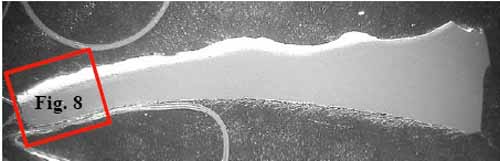
7. Location F1, oxalic at 4.5x magnification. Courtesy: David N. French Metallurgists
8. Location F1, fracture face at 42x magnification. Courtesy: David N. French Metallurgists
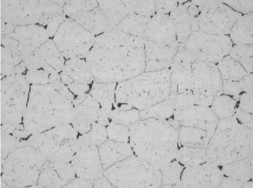
Location F2 also had intergranular cracks with some of the grains missing at the tube OD due to pull-out during polishing (Figure 9). In Figure 10, the microstructure shows sensitized austenitic grains with large carbides along the grain boundaries. Sensitization occurs from 800F to 1,500F, with the most rapid sensitization at 1,200F.
9. Location F2, intergranular cracks along the grain boundaries at the OD at 200x magnification. Courtesy: David N. French Metallurgists
10. Location F2, sensitized grains, mid-wall at 400x magnification. Courtesy: David N. French Metallurgists
Similar carbides were observed in the mid-wall away from the failure at Location B (Figure 11). Although sensitization decreases the corrosion resistance, it does not affect the mechanical properties significantly.
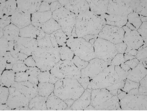
11. Location B, sensitized grains, mid-wall, 12:00 at 400x magnification. Courtesy: David N. French Metallurgists
Ring samples (Figure 12) were sectioned from the tube for dimensional and hardness measurements. The tube had thinned significantly: Ring A is 72% of MWT at the 2:00 position, and Ring B is 48% of MWT at the 12:00 position. The hardness, averaging 83 Rockwell B (RB), is slightly above the range for new SA-213 TP304H, 72-81 RB, as expected for material that has been carburized.
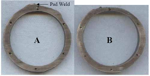
12. Sectioned rings. Courtesy: David N. French Metallurgists
Elemental analysis was performed on white deposit that was scraped from the OD surface. Analysis was via energy dispersive spectroscopy in the scanning electron microscope (see ASTM E1508-98) [10]. The carbon and sulfur content was determined by combustion analysis (ASTM E1019-03) [11]. The results are summarized in Table 2. The deposit was primarily iron oxide. Chromium, nickel, and manganese were likely from the steel. High amounts of carbon and sulfur indicate the possibility of reducing conditions. Unburnt carbon due to reducing conditions resulted in carburization of stainless steel tube. Potassium, sodium, and vanadium in the deposit point to the presence of low-melting species (such as V2O5-Na2O, V2O5-K2O, V2O5-Na2SO4, and V2O5-K2SO4) which may have contributed for significant wall loss. Calcium and phosphorus, from water or water treatment chemicals, were formed after the tube failure. Minor amounts of arsenic, magnesium, titanium, and chlorine were also detected. The white color may be associated with aluminum and silicon in the deposit.
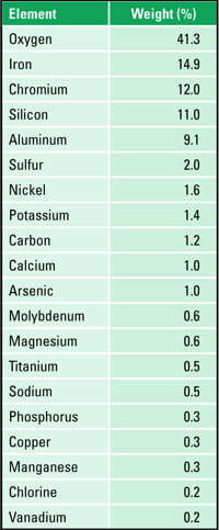
Table 2. Constituents of the whitish reheater tube OD deposit. Source: David N. French Metallurgists
The reheater tube failed due to oil ash corrosion, resulting in thinning and creep. Reducing conditions caused carburization of stainless steel. The microstructure had transformed to carbides along the austenitic grains. Carburization and sensitization contributed to a reduction in corrosion resistance that resulted in significant wall loss. The OD deposits also point to the presence of low-melting compounds that caused oil ash corrosion.
Case 3: Oil Ash Corrosion of a Superheater
A secondary superheater tube was received for metallurgical characterization. The tube was specified as 2.125-inch OD x 0.420-inch MWT, SA-213 T22 Cr-Mo steel. It had been in service for 43 years. Figure 13 illustrates the as-received tube with specimen locations, and the tube ID view. The oxide scale is seen at the ID. Some roughening and pitting corrosion were observed on the OD.
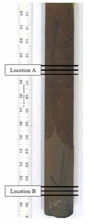
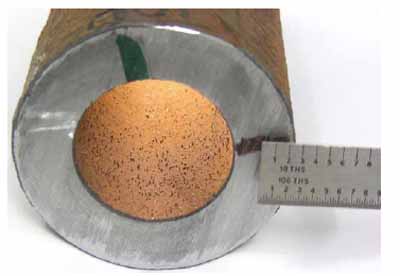
13. As-received tube with specimen locations illustrated and the ID view. Courtesy: David N. French Metallurgists
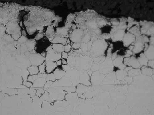
Figure 14 is the close-up view of pitting corrosion that had occurred on the OD. A specimen was circumferentially cross-sectioned to determine the depth of pits. Figure 15 is the close-up view of alligator hiding due to oil ash corrosion. A longitudinally cross-sectioned specimen was examined to determine the significance of oil ash corrosion at Location B.
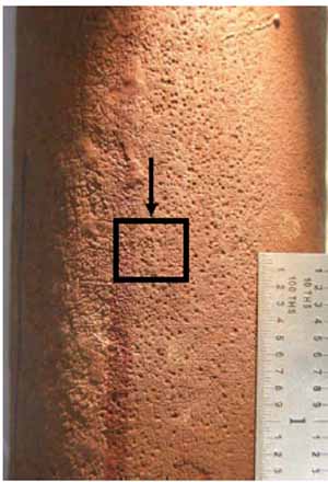
14. Close-up view of pitting corrosion at Location A at 3:00. Courtesy: David N. French Metallurgists
The pits observed in Figure 14 were shallow, and there was some intergranular attack along the grain boundaries, as shown in Figure 16. The alligator hiding (circumferential ridges) shown in Figure 15 was measured, and the deepest oil ash corrosion was 15 mils from the OD (Figure 17). The cycling of metal temperature causes ash layers to form and shed, leading to the alligator hiding. These circumferential grooves from the tube OD are typical for fireside corrosion. No creep damage was seen at the OD or at the tip of the groove. This area of the tube was exposed to the highest temperature, making it more likely to have oil ash corrosion.
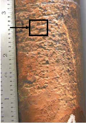
15. Close-up view of alligator hiding at Location B at 1:00. Courtesy: David N. French Metallurgists
16. Location A, 3:00, superficial pit, OD at 100x magnification. Courtesy: David N. French Metallurgists
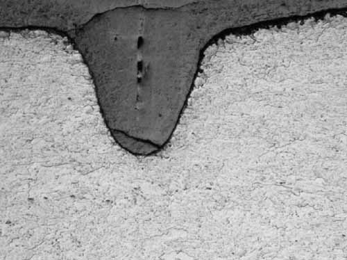
17. Location B, 1:00, 15 mils depth of ash corrosion, OD at 100x magnification. Courtesy: David N. French Metallurgists
The microstructure had transformed to ferrite with spheroidized carbides due to years of service (Figure 18). Similar microstructure was observed irrespective of the specimen location.
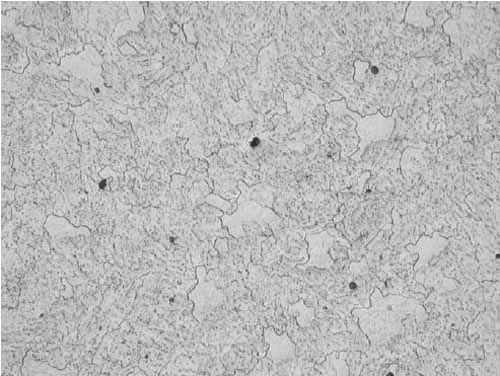
18. Ferrite with spheroidized carbides, Location B, 12:00, mid-wall at 400x magnification. Courtesy: David N. French Metallurgists
The thickest scale was measured as 20 mils (Figure 19). Based on the oxide thickness and years of service, the tube temperature was estimated as 1,064F. This temperature is below the recommended maximum for T22 material, 1,075F, but 43 years ago the maximum temperature may have been 1,125F. The operating temperature was within the susceptible temperature range for formation of low-melting-point constituents in oil ash corrosion, 1,000F to 1,500F. The low-melting compounds in oil ash corrosion are V2O5-Na2O, V2O5-K2O, V2O5-Na2SO4, and V2O5-K2SO4. Unlike coal ash corrosion, these compounds do not thermally decompose at higher temperature.
19. Location B, 6:00, ID with 20 mils of scale at 100x magnification. Courtesy: David N. French Metallurgists
Superficial pitting and some alligator hiding were observed on the OD of the superheater tube due to oil ash corrosion. V2O5-Na2O, V2O5-K2O, V2O5-Na2SO4, V2O5-K2SO4, or reducing conditions inside the furnace may have contributed to alligator hiding in this superheater tube. The tube microstructure had transformed to ferrite with spheroidized carbides after 43 years of service.
More to Come
In Part II we’ll explore several more case studies, including ash corrosion of a superheater and fireside corrosion of a water wall tube.
-Dr. Rama S. Koripelli ([email protected]) is metallurgical engineer, Dr. David C. Crowe ([email protected]) is technical director, Dr. David N. French is founder, and Jonathan Brand ([email protected]) is a senior metallurgical technician for David N. French Metallurgists.