The Evolution of Steam Attemperation
The fundamental design principles and process for modern steam desuperheating, or the attemperation of superheated steam in the power generation industry, have been evolving since the early 1930s. Meeting the requirement for steam quantity, quality, and temperature consistency is the foundation of traditional attemperator component design, particularly for fast-response combined cycle plants.
Increases in steam and combustion turbine operating temperatures and capacity that are inherent in the quest to increase steam cycle efficiency are advancing metallurgy technology. At the same time, diverse operational requirements—including cycling and low-load and load-following operations—have added complexity to the design of today’s combined cycle (CC) plants. Increased final superheated steam volumes and temperatures coupled with these diverse operational modes are, in turn, challenging many other vital plant components and systems, particularly the steam attemperator system.
Attemperator Design Overview
An excellent attemperation system for a modern CC plant requires a balance of design efficiency, component flexibility, and system reliability. Rapidly varying load conditions place strenuous duty cycles on steam attemperation components and downstream apparatus. On average, the attemperator system will experience 700 to 1,000 thermal cycles per year of normal operation. The thermal cycles can double in a cycling unit.
Most modern heat-recovery steam generation (HRSG) superheated steam attemperator component designs can be characterized as either circumferential, probe, or a combination of both technologies. As with many complex engineering components, designs evolve from functional requirements derived from expected plant operations. Each of these design categories has a unique set of requirements that must be met to achieve expected levels of plant performance and efficiency.
One of the more common superheater attemperator designs used in the HRSG CC market today is a circumferential spray design (Figure 1). The primary function of this design is to inject water perpendicular to the steam flow through multiple fixed or floating spray nozzles via a penetration in the main steam pipe wall and the attemperator’s inner spray liner or protective shield located inside the pipe. The nozzles produce mechanical atomization of the water droplets into the superheated steam flow. This design will often utilize external circumferential piping to the main steam pipe for water supply to the individual spray nozzles in conjunction with a remote spraywater control station.
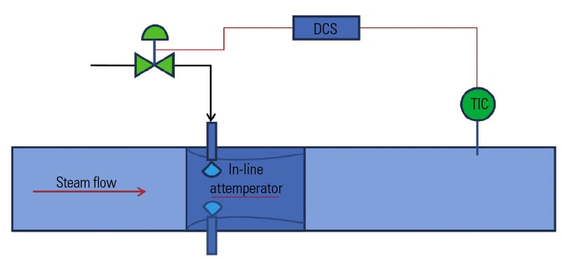
1. Circumferential in-line attemperator. In this design, water is injected perpendicular to the pipe steam flow through spray nozzles to desuperheat steam. Source: Tyco Valves & Controls
An alternative design for steam temperature control integrates a probe unit within the pipe. This design is divided into two major categories: integrated units (IU) and separated units (SU). Integrated probes incorporate the spraywater control valve function within the component (Figure 2). SUs offer a probe-style spray for water atomization with a remote spraywater control valve and external water supply piping (Figure 3). The probe application, whether of IU or SU design, employs single or multiple spray probes into the superheated steam flow, spraying water droplets parallel with the steam flow.

2. Probe-style IU desuperheater. In this design, an integrated flow control valve is inserted into a pipe through which water is injected into the flowing steam. A downstream probe measures the downstream temperature and is used to control the water flow. Source: Tyco Valves & Controls
Whether an attemperation system is circumferential or probe style in design, it must be supported by robust integrated control components and control functionality. The placement, design, and function of temperature probes are critical. A spraywater control valve or valves must enable “bubble tight” shutoff, and manual valves required for component and system isolation should be routinely inspected.
Most current HRSG steam attemperator systems are designed for minimal to zero water flow at maximum steam flow. CC plants that are dispatched through automated load-following management systems or automatic generation controls will see constant superheated steam attemperation as load is increased or decreased to meet fluctuating megawatt demand. This mode of operational dispatch will stress existing design limitations of the attemperation system.
Common system and component failure issues associated with extreme cycling conditions are:
- Spraywater control valve packing leaks or packing blowout.
- Wetting or droplet impingement of downstream thermal probes.
- Nozzle spring failure.
- Nozzle cracking or erosion.
- Linear weld attachment (pin) cracking or complete line failure.
- Main steam pipe cracking.
- Foreign object damage to the steam turbine.
Engineering and Design Considerations
Attemperator system components are designed and engineered to an expected life span, based on detailed 3-D finite analysis computer models, operational case histories, material composition, and expected thermal cycles associated with each component. Some shortened component life in the steam attemperator system can be attributed to supporting operational systems, such as feedwater or condensate supply conditions, water chemistry, distributed control system (DCS) settings, or response times. These support systems are usually designed for no or minimum spray conditions at design or baseload conditions for maximum efficiency.
The attemperator system installed at a plant designed for baseload may exhibit much different operation when cycled. A functional field test often proves prior factory test settings to be inaccurate. The following is a minimum list of supporting systems and parameters associated with the attemperator that should be reviewed and/or inspected to minimize the chance of downstream damage:
- Feedwater or condensate supply pressure, flow rate, and temperature at the spraywater control valve during various load conditions, or at the attemperator probe if an integrated design is present.
- Thermal probes, operational temperature, and location specifications should be verified and/or tested.
- DCS logic settings should be consistent with plant operation. The dead band of the control signal should be within the required tolerance.
- Water chemistry should be known throughout the steam and condensate systems under various load conditions.
This equipment, if not originally designed for cyclical operation, can be redesigned or modified to better suit current operational conditions. Often, a presumed shortage of feedwater or condensate spray capacity can be attributed to a logic setting in the DCS for valve position, or for response at a predetermined load condition.
Additionally, if the plant infrastructure has been in service for a period of years and has experienced a series of routine control valve preventative and corrective maintenance actions, operators may observe a minor, incorrect spraywater control valve stem position setting. Thermal probes are often placed incorrectly during unit construction, resulting in probe wetting or water droplet impingement, which will result in inaccurate steam temperature measurement.
Locating the Attemperator
In addition to mechanical design and field operations, accurately predicting water droplet atomization is very important. However, measuring droplet atomization in the field is difficult. If atomization of spraywater into the steam system is negatively affecting the ability of the temperature probe to measure downstream steam temperature correctly, then severe overspray and underspray conditions can produce increased thermal cycles and component damage.
Thermal probe location is a first step in verifying or eliminating probes as a possible contributor to poor steam attemperator system performance. Here are two general rules for measuring and verifying the proper location of upstream and downstream attemperator thermal probes (in a straight pipe):
- The upstream thermal probe should be a minimum of five pipe diameters from the attemperator location.
- The downstream thermal probe should be a minimum of 20 pipe diameters from the attemperator location.
These rules of thumb should be used as a quick check of an existing installation in straight pipe and are useful in determining if a gross error was made in thermal probe placement. Droplet atomization calculations can be used to determine the exact requirements and dimensions for the piping arrangement and thermocouple locations.
Advances in Steam Temperature Control
Precise steam temperature control has been a challenge for steam plant operators since coal was first shoveled into a furnace. Today’s superheat temperatures and daily plant cycling place extraordinary stresses on critical components. Effective steam temperature control is needed to protect expensive downstream equipment, such as the steam turbine.
In a typical CC plant, precise steam temperature control often conflicts with compact steam piping design. That makes it difficult to select an attemperator that can operate in the shortest possible straight length of pipe yet with an effective evaporation rate. This is particularly difficult when short pipe length is coupled with a high turndown ratio and the desire for a flat temperature distribution across the steam pipe.
Primary atomization of the feedwater used to attemperate the steam is produced by the nozzle design and geometry within the desuperheater and the pressure differential between the cooling water and the steam. Together with the University of Eindhoven in The Netherlands, Tyco Valves & Controls commissioned a joint research project to develop theoretical modeling of primary atomization using computational fluid dynamics (CFD) analysis and laboratory laser diffraction to analyze water droplet size upon discharge from the desuperheater.
The study examined two nozzle designs, spring-loaded and swirl nozzles. Initial results have identified that when operating at 25 bar (263 psi) with a 0.05 mm lift and Kv = 0.047 (Kv is a function of the nozzle design, and it relates the flow through a nozzle as a function of the fluid properties and the pressure drop across the nozzle), spring-loaded nozzles produce droplet sizes of 87 µm (the diameter of a human hair averages 30 µm). The same calculation for swirl nozzles at 25 bar, Kv = 0.043 resulted in droplet sizes of 27 µm—a factor of two to four times smaller than spring-loaded nozzles, depending on the operational pressure range. Basic engineering guidelines indicate that the smaller droplet sizes will evaporate faster and provide better desuperheater controllability.
Using this data, Tyco analyzed the secondary atomization characteristics evident when the speed differential and drag forces between the cooling water and pipeline media cause the droplets to split into smaller sizes. By measuring the speed differential of the two nozzle designs, Tyco is able to define which nozzle achieves higher speeds and therefore faster secondary atomization. Optimum atomization will result in frictional forces breaking the droplet size, which results in complete mixing and true temperature control and measurement.
The results of the Tyco desuperheater research study demonstrate that swirl nozzle designs offer enhanced performance and maximum use of water pressure drop for atomization in the shortest possible length. Optimized spray injection angles of swirl nozzles allow equal temperature distribution within the pipe and provide the highest turndown ratio using mass flow control, rather than pressure control. Having no springs or moving parts within the nozzle, and no pressure drop and cavitation in the control valve, maximizes the operational life cycle of the swirl nozzle design compared to spring-loaded nozzles.
Improving Desuperheater Design
The next generation of combustion turbines, HRSGs, and steam turbines will be able to operate at final steam temperatures that are projected to reach 1,150F. As steam temperatures rise, the need for tight steam control also increases, and multiple design solutions are required, depending on the specific modes of operation expected from the plant. At these higher steam temperatures it is imperative that potential weak points in a steam temperature control system are identified before it is installed in the field. That means relying on modern engineering techniques, 3-D design simulations, and the use of CFD and finite element analysis (FEA) tools.
For example, using CFD and FEA allows effective spacing of the nozzle openings to prevent areas of high stress. These tools can then be used to confirm whether the spray water nozzles are designed at the optimum angle for the shortest evaporation time and the reduction of cold spots on the inner steam line, which could lead to pipe cracking. Understanding the stress of higher cycling on the attemperator system and desuperheater nozzle units helps engineers to avoid future mechanical stress-related failures and maximize system life.
CFD modeling techniques also enable close examination of the droplet distribution within the pipeline from both probe-style and circumferential desuperheaters. This identifies which design offers more equal droplet distribution between the hot steam flow and cooling water and therefore faster and more effective evaporation. Using CFD analysis provides greater understanding of attemperator system design and how altering desuperheater geometry and spray nozzle angle can improve droplet evaporation and minimize impingement on the pipe wall.
FEA offers particular advantages during the design and engineering phase of the project by analyzing the heating and cooling cycles of critical desuperheater components. Attemperator components in the hot zone are at increased risk of thermal fatigue and shock. Using an FEA program, Tyco can identify where a crack may appear in, for example, the desuperheater nozzle and predict the potential failure point over the service life of the product.
Taking its steam temperature control testing further, Tyco has carried out thermal fatigue cycle analysis on its desuperheater nozzle injection units in two material types—F91 and Inconnel 718—at steam temperatures up to 1,150F, water temperature of 307F, and up to 10,000 thermal cycles. These analysis tools have allowed Tyco to improve the design geometry and metallurgy of its severe service desuperheaters, which then allow engineers to produce a design that will minimize stress points and optimize the design and engineering characteristics of the attemperator system (Figure 5).

5. TempLowHT flow path. TempLowHT incorporates a spraywater control valve located outside the heat-affected zone, reducing the risk of thermal shock to critical components. A single probe provides water droplet atomization through a series of nozzles located parallel to the steam flow. Source: Tyco Valves & Controls
The Future of Steam Attemperation Technology
Drawing on the results of the water droplet study, CFD modeling, and FEA, Tyco has developed a new circumferential steam attemperation system for the power generation industry. CircTemp has been designed and engineered to improve desuperheater performance in severe-service boiler system applications. In developing the product, Tyco used the advanced modeling techniques to establish the performance characteristics and operational parameters. CircTemp’s design uses the high-temperature, high-cycling experience Tyco has gathered through its Narvik-Yarway TempLowHT probe desuperheater and applies it to the new product development.
Tyco started with a nozzle design that provided good primary atomization, ensuring that droplets would only become smaller during secondary atomization with the shortest possible evaporation time. This approach has reduced water droplet sizes from 100 µ to 20 µ, delivering shorter evaporation times. The key is the higher turndown ratio achieved by the CircTemp desuperheater, compared with typical spring-loaded nozzle circumferential designs. Using mass flow, rather than a pressure-reducing control valve, maintains a constant pressure differential within the attemperator system. This increases the velocity of the water discharged from the nozzle injection unit, producing smaller water droplets. In spring-loaded nozzle designs, the control valve is the limiting factor because the pressure after the valve determines the discharge velocity.
The CircTemp design enables individual nozzles to be shut off as the steam load fluctuates. This means that a considerably higher turndown ratio can be achieved by sequencing nozzle open and closing. As the load increases, smaller nozzles and then larger nozzles can be opened one at a time, as the flow requires. When less flow is needed, the nozzles can be closed in the reverse sequence: first the largest and then the smaller nozzles.
Tyco’s study into optimum spraywater angles also determined that cooling water entering the pipe perpendicular to the steam flow could impinge on the pipe wall. Optimized spray angles and nozzle configuration creates different cooling water spray patterns and ensures equal distribution. This research into desuperheater spraywater characteristics has influenced the CircTemp design to prevent potential damage to downstream pipe and liners by eliminating cold spots on the inner pipe wall and maintaining constant steam temperature.
Striving for higher CC plant efficiency means higher steam temperatures and, probably, high cycling duty over the lifetime of a plant. Components in direct contact with the higher-temperature steam must have the best materials, be based on state-of-the-art research, and integrate field operating experience into their design and manufacture. One of those components, the critical yet problematic desuperheater valve, is ready today for the next generation of combined cycle plants.
— Martin-Jan Strebe ([email protected]) is director for global product management control valves and Arvo Eilau is marketing manager, Tyco Valves & Controls. As of October 1, 2012, Tyco Valves & Controls will be officially known as Pentair Valves & Controls.