Strategies for Inspecting HRSGs in Two-Shift and Low-Load Service
Inspections of more than 500 units over the past 10 years reveals common challenges faced by mid-life HRSGs, particularly those used in combined cycle plants to offset renewable generation and other aggressive operating strategies.
A heat-recovery steam generator (HRSG) is much like other power generation equipment—run it at design conditions and chances are it will run with high availability and require only routine maintenance for many years. Mechanical problems within the HRSG are usually site- and vendor-specific, but experience has identified many common failure modes. The most common cause of HRSG failures (after malfunctioning equipment such as sprays or duct burner controls) is a change in operating profile, typically from base load to daily cycling, especially in markets with must-run wind generation. Although a change in operating routine doesn’t automatically translate into gross degradation in HRSG reliability, pressure parts are often susceptible to having less design margin and more vulnerability to consequential damage caused by other equipment.
This article identifies common unit failure mechanisms you should consider when developing your HRSG inspection strategy for low-load operations and two-shift cycling.
Experienced Inspectors
Tetra Engineering Group Inc., has inspected more than 500 HRSGs over the past 10 years (many of which are F-class or G-class triple-pressure duct-fired units in two-shift cycling operation with reheat steam turbines), representing a cross-section of all the major HRSG manufacturers (see sidebar). About 70% of inspections were of large reheat HRSGs. The inspected units represent all North American Reliability Corp. regions as well as many units in emerging markets (Mexico), and the mature 50-Hz markets in Europe and the Middle East. Uniquely, many of the Middle East units are non-reheat units commonly integrated with a large desalination facility for integrated power and water operations.
HRSG Inspection ToolkitA thorough inspection of a large, two-shifted heat-recovery steam generator (HRSG)—for example, behind a GE Frame 7FA, or Siemens W501F/G—with reheater, typically requires about two days for a three-man crew, which includes a field supervisor, an HRSG engineer, and a nondestructive testing technician. These inspections are more detailed than boiler insurer statutory inspections or inspections by appurtenance suppliers of non-pressure part components. The inspection of a typical mid-life HRSG includes:
|
Our inspections have revealed that, over time, most units experiencing rapid thermal gradients (as a result of two-shift cycling) present stress-related failures (for example, creep, corrosion fatigue, or stress corrosion cracking) in tubes, headers, and structural steel. Frequent startups also make it challenging for operators to maintain water chemistry within acceptable limits, which results in greater risks of single- and two-phase flow accelerated corrosion (FAC) damage.
The changing thermodynamic characteristics of steam during startup conditions also produce component stresses and excess condensate that must be quickly drained. Less condensate is produced during fast startups, though more attemperation spray may be required to control steam pipe metal temperatures than when undergoing a routine startup. Low-load operations usually use more attemperation spray to control steam pipe metal temperatures than when undergoing a standard startup. Since low-load operations are generally at substantially lower pressures, this also offsets some of the more aggressive thermal characteristics of two-shift cycling under low-load operations. Many HRSG designs present condensate removal challenges during either type of start, which is a characteristic that varies greatly between HRSGs, even those built by the same manufacturer.
Under cycling conditions, other undesirable side effects are also possible, such as greater risk of water hammer in the reheat piping, thermal quenching of hot component surfaces due to spray valve degradation, and leakage or failure of the pressure boundary at tube-to-header welds, riser piping to drums, crossover (connecting) piping, and drain connections. Temperature control (heat tracing and in some cases portable heaters) may also be required to prevent tube and header failure during freezing conditions. Several two-shift plants experienced thermal quenching or brittle fractures during the cold winter of 2013 to 2014.
HRSG Inspection Guide
In the future, HRSG inspections must become more comprehensive and identify critical damage earlier, all while being conducted during fewer and shorter outages. The following sections discuss and illustrate specific failure mechanisms that must be quickly identified, beginning with the greatest impact on forced outages and performance degradation (although several categories have been combined for the sake of brevity). An online supplement has also been provided that contains additional photos and further discussion of common failures that should guide a HRSG inspection.
Grade 91 Components. Most large HRSGs constructed since the late 1990s have tube panels, interconnecting piping, outlet steam manifolds, and in some cases bypass piping constructed from Grade 91 creep-strength enhanced ferritic (CSEF) steel. Fabrication, welding, post-weld heat treatment, and performance problems with Grade 91 (and other CSEF steels) have been well documented. Aggravating the problem, maximum metal temperatures may increase slightly following combustion turbine (CT) upgrades to accommodate fast starts and low-load operations.
Hig-Temperature Tube Leaks and Failures. The most significant damage that occurs to HRSG components inside the casing is generally leaks and failures of pressure parts, principally tubes, headers, and connecting piping (Figure 1). Tube failures are the dominant cause of lost plant reliability. While tube repairs are not always lengthy procedures, they contribute substantially to the cost of two-shift cycling duty. In today’s merchant markets, a forced outage can be a costly consequence of aggressive operation without sufficient monitoring of component degradation.
 |
| 1. Leaky weld. A leaking 16-inch-diameter reheater crossover pipe in a cycling unit is shown. Courtesy: Tetra Engineering Group Inc. |
High-temperature tubes experience leaks and failures due to creep, thermal fatigue (and combinations of both), quenching, and inadequate condensate removal. Also, high differential thermal stress due to exhaust gas bypassing tube panels, side-wall or central baffles failure, or other plant transients such as single pull tensile overload, has resulted in many tube failures in certain reheater designs.
The most common tube damage mechanism is bowing, which is usually caused by differential thermal stress, quench, manufacturing variations in tube length, and the like. Inspections of new units sometimes identify small tube bows present prior to operation. Many units exhibit bowing of reheater tubes, especially those located below attemperator sprays or in the first pass downstream of duct burners. In some cases, tube bowing doesn’t change substantially over many years, but other units have experienced “ratcheting” of tubes to the point where the tubes kink and develop local yielding that necessitates repair or replacement.
Flow Accelerated Corrosion Thinning. Perhaps the most notorious of HRSG tube failure mechanisms is FAC. FAC wall thinning of pressure parts has been aggressively addressed in the nuclear industry, where several catastrophic failures occurred in susceptible piping. The fossil-fueled power generation industry has experienced FAC to a lesser degree in external feedwater heaters, attemperator spray valve downstream piping, feedwater pump discharge piping, and steam turbine extraction lines. Units with poor water chemistry control, extensive layup periods, or particular design configurations are especially susceptible.
With a combined cycle fleet of large units fast approaching mid-life, many have experienced some FAC wall thinning. The primary areas where FAC thinning occurs in HRSGs is either internal (tubes and headers) or in boiler connecting piping (evaporator risers, short feedwater piping segments between the pumps, and the economizer inlets). Also, there is a sizeable two-phase steam/water exposure in low-pressure (LP) and intermediate-pressure (IP) components. This is in contrast to conventional boiler experience, where FAC is largely confined to feedwater lines that have piping and feedwater heater components.
The best approach to managing FAC thinning is a combination of excellent water chemistry control and vigilant trending of component wall thickness in susceptible regions (most of which are inside the HRSG casing). External feedwater piping can also be susceptible for combined cycle plants that take feed pump suction from the LP drum.
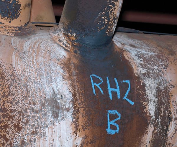
Thick Section Components. Leaks and failures in larger components such as headers, major connecting piping, and steam piping can require lengthy outages with significant repair costs and commensurate loss in operating revenue while repairs are completed. There have been instances of header leaks due to long-term layup with inadequate water chemistry control or failure to drain and inert the waterside for extended periods. Grade 91 interconnecting piping at the high-pressure (HP) superheater or reheater (RH) outlet manifolds are experiencing increasing numbers of leaks due to inadequate material properties, poor shop and field welding practices, and improper post-weld heat treatment (Figure 2).
 |
| 2. Cracked and dangerous. This Grade 91 hot reheat upper header link to the outlet manifold cracked during operation of this two-shifting plant. Courtesy: Tetra Engineering Group Inc. |
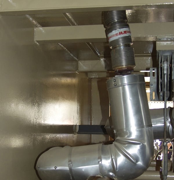
Water Hammer. Water hammer has occurred at many combined cycle plants. It is often attributed to a combination of problems related to steam or spray valve control, inadequate drainage of condensate, or abrupt valve actuation. Water hammer is generally a destructive transient; casualties typically include adjacent piping supports, with yielding of steam piping a common end result (Figure 3). Good practice is to apply nondestrutive testing inspection to components adjacent to the most heavily damaged areas in order to assess whether a crack exists that requires repair.
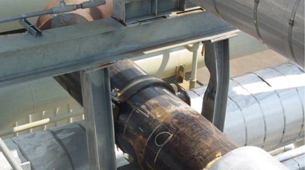 |
| 3. Hammered pipe. Water hammer can cause significant damage to HRSG steam piping. In this unit, water hammer damaged its cold reheat piping and supports. Courtesy: Tetra Engineering Group Inc. |
Casing, Liner, and Gas Baffle Damage. A frequent damage mechanism encountered in old and new units is damage to gas baffles. Due to the nature of their geometry and proximity to a variety of potential interferences, these structures are often subject to fatigue, distortion from thermal expansion, interference, and high vibrations, particularly in the hot sections of the HRSG.
While some HRSG designs have no central baffles, those that do have experienced frequent damage. While most exhaust gas continues to pass through the tube panels, the lower flow resistance along unblocked “lanes” can result in downstream tubes experiencing significantly hotter conditions than neighboring tubes. This flow and temperature imbalance can cause very large differential thermal stresses or a high local increase in water/steam velocity, especially in evaporator sections. That in turn can aggravate FAC wall thinning, which is found to be worse on the tubes located at the end of tube panels (closest to the “open” area normally protected by gas baffles).
Quench Damage. Condensate formation during startup is another well-known cause of tube and header leaks and failures. Some units have experienced repeated tube failures, extreme tube bowing, and related problems with attemperation spray equipment. One approach has been the installation of temporary thermocouples to more accurately determine the temperature variations in reheater and superheater tubes, which in turn can be used by operators to better manage startup temperature transients.
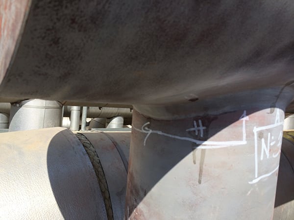
Boiler and Steam Piping Damage. Problems with boiler and steam piping are often associated with the reheat piping, particularly in units where attemperator sprays have been designed with too-short downstream straight pipe lengths (less than 10 pipe diameters). Incomplete atomization of attemperator sprays sends liquid droplets downstream that impact piping surfaces, which causes significant localized thermal stresses and may ultimately result in weld cracks (Figure 4).
 |
| 4. Steam leaks. Generally, larger thermal stresses shorten the fatigue life of affected components, particularly drums, thick section headers, and tube-to-header welds. The photo shows a cracked reheater link transfer pipe manifold that failed in a unit operated in two-shift cycling. Source: Tetra Engineering Group Inc. |
Drain Leaks and Failures. Drain pipe failures are another relatively common category of problems found in mid-life units. Drains are sometimes cocked or otherwise bent during final construction when the pre-fabricated tube panel assemblies are field-connected to the drain system (Figure 5). The result is drain welds that are often under considerable stress due to misalignment in their casing holes and misalignment of drain tube stubs with the field drain work.
 |
| 5. Out of shape. Bending of this high-pressure superheater drain was experienced due to misalignment during construction. Courtesy: Tetra Engineering Group Inc. |
While relatively easy to repair, drain leaks have been known to cause boiler drum level instability that resulted in an emergency plant shutdown. Inspection of accessible drain welds during scheduled HRSG inspections is an effective way to reduce the likelihood of a drain failure during operation.
Drum and Internals Damage. Damage to drum surfaces and internals includes problems with baffle weld designs and accumulation of tubercle deposits over pits in HP and LP drums and some small defects in drum shell surfaces. Inspection of new units may typically find no incidents of severe corrosion of steam separation devices, development of fatigue cracks, or other serious damage. Units in mid-life operation may experience cracking of drum-to-downcomer nozzles or to feedwater supply piping. Sludge piles are often evident in LP drums where iron transport is a problem due to inadequate control of oxygen levels.
Stress Corrosion. Another damage mechanism that has caused tube failures in cold end components is stress-corrosion cracking. This damage mechanism affects susceptible materials and can result in tube leaks or failures after just a few years of operation. Deposits on the inside diameter (ID) of the pipe that tend to protect and concentrate aggressive chemical species are commonly found. Accumulation of deposits on the tube ID implies problems with feedwater water treatment and control.
Cold End Bowing. Occasionally, bowed tubes are observed in the cold end of large units. Sometimes the bowed tubes are near the feedwater inlets where the inlet water temperature may be significantly colder than adjacent tubes, depending on the flow pattern in the harp design. This can lead to large thermal stresses between tubes and potential failure.
Flow Distribution Device Damage and Failures. The internal tube arrangement of many HRSGs requires flow distribution devices. Their specification depends on a variety of factors related to the CT, geometry of the transition duct, and general layout of the HRSG, such as the order, number, and arrangement of tube modules. Problems are common with flow distribution devices, especially those installed upstream of the lead tube bank, where they are often needed to re-distribute flow to higher tube elevations. In some cases a second flow distribution grid is installed upstream of duct burners to further redirect the exhaust gas flow, although this is not common.
The most common design is a perforated plate, although large turning vanes and smaller sets of turning vanes are often used. The most common problem for a perforated plate is fatigue damage that is attributable to high gas velocity and inadequate structural support to hold the perforated plate in position. Often the support structure behind the plate experiences widespread fatigue failure followed by metal fatigue in the ligaments between the holes in the perforated plate. In the extreme, flow distribution devices have collapsed and become an obstruction in the gas path.
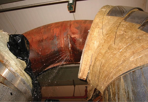
Duct Burner Issues. Duct burners are used to increase steam production, either to compensate for reduced CT output due to high ambient conditions or for additional (peaking) steam production. Local overheating of tubes has been attributed in some cases to excessive duct firing. Other problems with duct burners have involved the burner elements themselves either being improperly positioned or falling out of their supports during operation so they were no longer supported at both walls (Figure 6). In some instances the accumulation of condensate in burner runners during periods of long layup has caused operational problems. ■
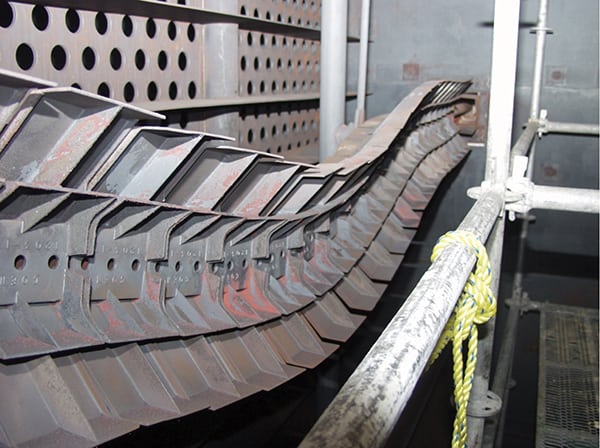 |
| 6. Bent burner. In extreme cases, the duct burner runners are so damaged that replacement is the only option. Courtesy: Tetra Engineering Group Inc. |
— Peter S. Jackson, PE ([email protected]) is director, field services, David S. Moelling, PE ([email protected]) is chief engineer, and James W. Malloy ([email protected]) is managing director (Europe) for Tetra Engineering Group Inc.