SO3 Control: Dominion Demonstrates CleanStack Technology
Dominion Generation (DG) has installed selective catalytic reduction (SCR) systems on many of the large coal-fired generating units it operates. The catalyst used has an SO2 to SO3 oxidation rate of about 1%, which roughly doubles the SO3 concentration at the outlet of the boiler economizers. The magnitude of the increase was proportional to the sulfur content of the coal being burned.
DG has committed to installing wet scrubbers on the four coal-fired units of the Chesterfield Power Station 15 miles south of Richmond, Va., to significantly reduce SO2 emissions. Chesterfield Station has four coal-fired units built between 1952 and 1969 that are powered by tangentially fired boilers originally supplied by Combustion Engineering (now Alstom Power) and turbine-generators from General Electric. The units have a total capacity of 1,298 MW. SCRs have been installed on Units 4, 5, and 6.
A wet flue gas desulfurization (FGD) system and a fabric filter baghouse are to be placed in service on Unit 6 by June 2008 (Figure 1), and a common wet scrubber serving Units 3, 4, and 5 will be placed in service by December 31, 2010. The retrofits will make it possible to burn lower-cost, higher-sulfur coals. The combination of higher-sulfur coal and SCR can result in an all-too-familiar consequence of retrofitting coal-fired units with SCR systems to reduce their NOx output. If not reduced before reaching the stack, excessive SO3 concentrations in flue gas can severely shorten fabric filter bag life and can make a power plant’s emissions higher in particulate matter and more opaque. Under certain conditions, the emissions can become opaque enough to create an unsightly "blue plume" that could also touch down in the local community.
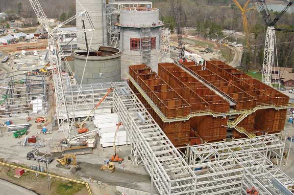
1. A baghouse and scrubber are under construction on Chesterfield Power Station Unit 6. Courtesy: Dominion Generation
In each of the Chesterfield units, the gas temperature at the outlet of the air preheater (APH) is about 290F. Accordingly, the project design team wanted to reduce the SO3 concentration at the baghouse inlet from the new level of 40 ppm to between 5 ppm and 7 ppm. This would correspond to an acid dew point temperature between 250F and 270F, providing a 20-degree operating margin and eliminating concerns about bag life and blue plumes.
Having specified the performance requirements of the SO 3 control technology, DG then spelled out three operating criteria it would have to possess:
-
No negative impact on unit operations, such as plugging of the APH or an increase in the pressure drop across it, or accumulation of sorbent in back-end duct work.
-
Use of a low-cost sorbent.
-
High levels of reliability, operability, and maintainability.
Make a Choice
DG considered using each of three types of available SO 3 abatement technologies: fireside reagents, reagent-based postcombustion additives, and wet electrostatic precipitator (ESP) technology. But none met all of the performance and operating criteria, so they were ruled out.
At the time, the University of North Dakota’s Energy & Environmental Research Center had been working with Marsulex Inc. (www.marsulex.com) and Alstom Power’s Air Preheater Company (www.airpreheatercompany.com) to develop solutions to the very problem that the Chesterfield plant faced: increased SO3 emissions from boilers. The three organizations had recently developed and modeled the concept behind what came to be known as CleanStack technology.
CleanStack promotes condensation of SO3 by injecting ultrafine particulate material (<4 microns in diameter) immediately upstream of the APH (Figure 2). The particle concentration provides nucleation sites for condensation of sulfuric acid formed from SO3 and moisture in flue gas. The condensation process does not depend on the composition of the particles but only on their concentration and the particle-size distribution. By substantially increasing the concentration of small particles in combustion flyash (typically, from 1.5% to 3% to 4% by weight), the process aids in SO3 removal.
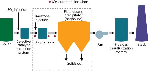
2. Injection and sampling locations for the CleanStack SO3reduction technology. Source: Dominion Generation
DG decided to conduct a full-scale demonstration of CleanStack on Chesterfield Unit 5. The goal of the project was to demonstrate the effectiveness of the technology at removing SO3 from flue gas as a function of limestone feed rate and flue gas SO3 concentration. For the testing phase of the demonstration, finely ground limestone with particle diameters of 2 to 3 microns was chosen as the reagent, to provide a degree of acid neutralization after condensation has occurred.
Testing and Sampling Parameters
Unit 5 of Chesterfield Station is rated at 350 MW (nominal) when firing 183,000 lb/hr of bituminous coal. Its split-backpass design accommodates both SCR systems for NOx control and cold-side ESPs for particulate removal. DG had previously upgraded the APHs of Unit 5 with advanced heating elements, which were intended to minimize fouling by ammonium bisulfate formed as a by-product of ammonia slip from SCR operation. These same heating elements are recommended for the CleanStack process.
The testing, which was performed during the summer of 2006, sought to determine:
-
The baseline SO3 concentration at the APH inlet, APH outlet, and ESP inlet.
-
The particle-size distribution and feed rate of the limestone injection system, which uses multicyclones.
-
The efficiency of SO3 removal across the APH and at the inlet to the ESP at different limestone injection rates.
For testing purposes, a commercial SO3 generator that the plant uses for ESP conditioning was called on to catalytically generate an elevated SO 3 concentration (~35 ppm) similar to that produced by firing of a higher-sulfur coal with an SCR system in service. The SO3 was injected into the flue gas far enough upstream of the APH to ensure its uniform dispersion.
Limestone was injected upstream of one of the APHs and ESPs of Unit 5, using a system with the configuration shown in Figure 3. It was drawn from the storage silo (Figure 4) into an attritor mill and then into an air classifier. The classifier sends oversized particles back to the mill for regrinding while delivering fine particles (with a mean size of about 3 microns) to the cyclone collector. Fine limestone then is pneumatically conveyed to the distribution manifolds and injection lances upstream of the APH inlet. Twelve limestone injection lances were used to provide a reasonably even distribution across the gas stream entering the APH.

3. Configuration of the limestone injection system. Source: Dominion Generation

4. The limestone silo used during CleanStack testing. Courtesy: Dominion Generation
SO3 sampling was performed at three locations: the inlet to the APH (downstream of the SO3 injection location), the exit of the APH, and the inlet to the ESP. All SO3 sampling was done using the controlled condensation method. At each location, four ports were sampled across the duct for one hour each (two ports were sampled simultaneously), providing a four-point traverse. The SO3 concentration reported was the average across the four ports. The SO3 concentration in the sample collected at each point was measured using ion chromatography. To compare the results from each of the sampling locations, the data were put on the same O2 basis (3%, as measured by a portable analyzer at each sampling location).
Table 1 lists the testing parameters. During the testing, Unit 5 was operated at nearly full load.
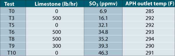
Table 1. Testing parameters. Source: Dominion Generation
Test Results
Table 2 lists the SO3 levels measured in Unit 5’s flue gas during six tests. The results are presented on a constant O2 basis (3%) to allow "apples to apples" comparisons of concentrations at each of the three sampling locations and determinations of the actual effectiveness of SO3 removal.
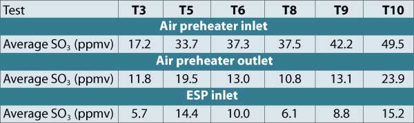
Table 2. Flue gas SO3 concentrations (3% O2 basis). Source: Dominion Generation
The data in Table 2 show differences in SO3 concentration across the duct, especially at the APH inlet. In general, the concentrations at the C and D ports were higher than those measured at the A and B ports. This was found to be the result of an uneven distribution of SO3 flows being injected into the duct. The variability in the SO3 levels at the outlet of the APH was due to its rotation. Previous modeling predicted this effect, as well as the effect on SO3 concentration and removal of variations in temperature caused by APH rotation.
At the ESP inlet, the SO3 levels were more constant across the duct due to the longer residence time, which allows better mixing of the gas. The SO3 level at the APH outlet for test T3 was similar to that observed during the other tests, where limestone was added.
Table 3 and Figure 5 compare the results of testing with and without limestone injection. On average, limestone injection reduced the SO3 concentration at the ESP inlet by 49.3%.
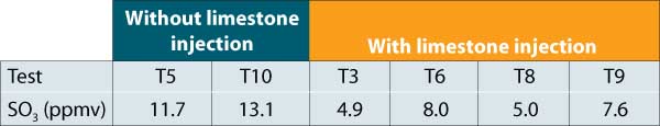
Table 3. Test results, with and without limestone addition. Source: Dominion Generation

5. Test results show significant SO3 reduction. On average, limestone injection reduced the SO3 concentration at the ESP inlet by 49.3%. Source: Dominion Generation
Figure 6 compares the test results to model-predicted curves of SO3 flue gas concentrations for three cases: a baseline, and limestone injection at 300 lb/hr and 500 lb/hr. At the ESP exit, a substantial reduction in gas-phase SO3 was predicted for the case with limestone injection (25%, versus 55% of the starting concentration). The difference can be attributed to condensation on particulate material. Although the limestone increases particle loading only from 1.5% to 3% to 4%, the small particle size produces significant additional condensation. The test results are generally in good agreement with the model predictions.
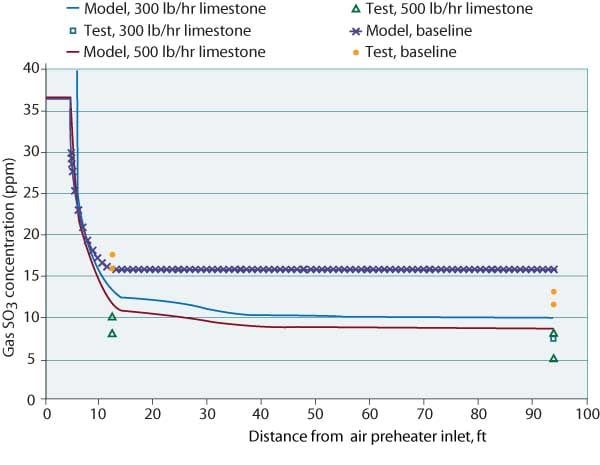
6. Comparison of test results with modeling predictions. The model assuemd an SO3 concentration of 36 ppm. Source: Dominion Generation
DG is now installing a permanent CleanStack system on the 680-MW Chesterfield Unit 6. The company also plans to install permanent systems on Chesterfield Units 4 and 5.
— Edward Bowes, PE is an engineering manager for Dominion Resources and can be reached at [email protected]. Robin B. Rhodes is vice president of Alstom Power’s Air Preheater Company. Dr. Bernard T. Hamel is a consultant with Marsulex Inc. Dr. Steven A. Benson is senior research manager, Dr. Donald P. McCollor is technical manager, and Dennis L. Laudal is senior research advisor for the University of North Dakota Energy & Environmental Research Center (www.eerc.und.nodak.edu).