Recycling, reuse define future plant designs
The Valley of the Sun went off the water wagon on March 4, ending a record 136 consecutive days without measurable rainfall. That first 0.05-inch sip, followed by a 0.18-inch gulp the next day, only left residents yearning for more. But Mother Nature was only teasing, because the rest of March remained dry. On March 29, Arizona’s drought threat level moved from “severe” to “extreme” due to nonexistent snow packs and one of the driest winters on record.
As the drought enters its 11th year, there are two pieces of good news. One is that the Colorado River, which supplies about one-third of Arizona’s total water supply, is at close to normal flows. The other is that local reservoirs, which hit 30-year lows early in 2005, are on the mend. But the bad news is that water supplies for power generation remain at a premium.
Demographers tell us that Arizona was the second-fastest-growing U.S. state (Nevada was No. 1) in the 1990s. Today, it has just under 6 million residents—more than twice the 2.7 million of 1980. The Arizona Department of Commerce predicts that the extraordinary growth will continue as the baby boom generation retires and that 8.5 million people will call the state home in 2030.
This rapid growth will increasingly strain Arizona’s water management and power generation infrastructures, which are already quite taxed. When all the air conditioners in Phoenix are cranked up to “max cool” on a 110-degree-plus day, the city’s residents and businesses use more electricity than Manhattan. For this reason, Arizona Public Service (APS) expects that it alone will need another 5,000 MW of generating capacity over the next decade. A reliable source of power and water capable of keeping pace with Arizona’s projected population boom is the only thing separating the state’s desert dwellers from a future of hot, thirsty summers (Figure 1).
1. Too many people. Growing baseload and peak electricity demand in the U.S. Southwest through 2008 will be met by expanding gas-fired generating capacity. Source: Salt River Project
Terrific template
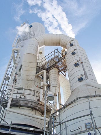
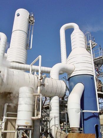
Generating lots of megawatt-hours without consuming lots of water is a difficult trick to pull off, but the Redhawk Power Station (Figure 2) has done it. Owned by APS, Redhawk is located 4 miles south of the Palo Verde Nuclear Generating Station, about 60 miles west of Phoenix.
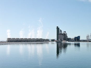
2. Desert dweller. The Redhawk Power Station is 4 miles south of the Palo Verde Nuclear Generating Station, about 60 miles west of Phoenix. Source: POWER magazine
The combined-cycle plant, which went commercial in 2002, has twin 530-MW power blocks. Each block consists of two General Electric 7FA gas turbines nominally rated at 165 MW (at 73F) and a single 200-MW steam turbine from Alstom Power. Redhawk’s two heat-recovery steam generators (HRSGs), supplied by NEM (now Louisville, Kentucky–based Vogt-NEM), are fired by duct burners so they can supply an additional 15 MW apiece when peaking power is needed during summer days. A selective catalytic reduction (SCR) system, from Hitachi Zosen Corp. with ammonia injection, keeps NOx emissions under the permitted limit of 3.0 ppm. All in all, Redhawk is a very well designed and solidly operated plant, as evidenced by its 96%+ availability factor during 2005.
Although Redhawk’s configuration is fairly standard, its water management systems—which reuse nearly 1 billion gallons of reclaimed wastewater each year—are anything but. Recycling water for all plant needs appreciably reduces the strain on already burdened local aquifers. In fact, Redhawk’s zero liquid discharge (ZLD) system all but eliminates liquid waste leaving the plant. Plant designs like Redhawk’s that generate clean, low-cost electricity within local environmental constraints set the bar high for power project developers eyeing the region.
More precious than power
The raw water makeup for the Redhawk plant begins its journey from the greater Phoenix area at the 91st Avenue Wastewater Treatment and Tolleson Wastewater Treatment Plants. There, treated effluent from these cities undergoes secondary treatment. The makeup water is propelled by gravity for the first 28 miles of the journey and then by pumps for the last 8 miles. Upon reaching the Palo Verde Water Reclamation Facility (PVWRF), the wastewater is treated a third time and put into a 760-million-gallon lined reservoir. It is water from this reservoir that Redhawk uses as plant makeup water.
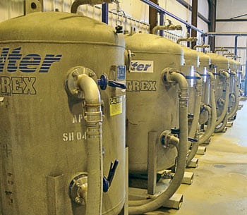
From the PVWRF reservoir, a 4-mile-long, 36-inch-diameter pipeline brings the makeup water to Redhawk and dumps it into a 163-million-gallon lined holding pond covering 42 surface acres. The average conductivity of the makeup water in the Redhawk holding pond (Figure 3) is typically 1,400 to 1,800 microsiemens (micromhos) per cm (µS/cm). As a backup to the main water source from the Water Reclamation Facility, Redhawk also has a water clarification system on standby, ready to be activated should the treatment of groundwater be required. To date, this system has only been used during commissioning, and never during normal operation. Figure 4 is a complete flow diagram of Redhawk’s makeup water system.
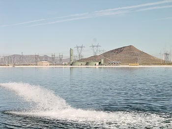
3. Triple-treated. Makeup water pumped from the nearby Palo Verde Water Reclamation Facility is stored in a 163-million-gallon holding pond. Standby water clarification treatment equipment seen in the background treats well water as needed. Source: POWER magazine
4. Balancing act. The sources and uses of water at Redhawk power station. Source: Arizona Public Service
Makeup water from the holding pond is the feedstock for the plant’s two cooling towers (one per power block) and single boiler water treatment system. As shown at the left of Figure 4, the process begins with the pumping of 2,240 gpm to each nine-cell cooling tower (Figure 5). The water sent to the towers typically has total dissolved solids (TDS) of 900 mg/l; inside the towers, its chemistry can cycle up to a maximum TDS of 20,000 mg/l. Cooling tower pH is maintained in the range of 6.9 to 7.5 by the injection of sulfuric acid. A dispersing agent is fed to maintain a dose of 10 to 20 ppm. Enough defoaming agent also is injected to eliminate visible foam in the sump. A continuous free chlorine residual is maintained at 0.2 to 1.0 ppm by plant operators.

5. Dedicated cooling. Each power block at Redhawk is served by a nine-cell cooling tower. All plant waste drains come back to the tower sumps. A slipstream from the sumps goes to the plant’s zero liquid discharge system. Source: POWER magazine
The remaining 520 gpm from the original 5,000 gpm feed from the makeup pond is sent to a 60,000-gallon reverse osmosis (RO) feed tank (bottom left of Figure 4), which serves as a buffer upstream of the boiler water treatment system.
No organics allowed
A key innovation in the Redhawk plant’s water balance design is the routing of virtually all plant drains and liquid waste streams (including HRSG blowdown and gas turbine drains) to the cooling tower sumps. One of the challenges of such a design is anticipating potential microbiological growth in these water lines. For this reason, any stream with any excess algae buildup—such as the backwash from the multimedia filter (MMF)—must be carefully managed. Redhawk eliminates any potential problems in this area by continuously injecting bleach upstream of the MMF to maintain the concentration of free chlorine residual at 0.4 to 0.8 ppm. Downstream of the filter, sodium bisulfite is injected to remove any residual chlorine as well as a nonoxidizing biocide and an antiscalant (Figure 6). Chlorine can destroy the thin-film RO membranes over time if it is not removed from the water.
6. Keeping bugs at bay. Several chemicals are added to the makeup water upstream and downstream of the multimedia filter to maintain residual chlorine levels. Source: POWER magazine
The makeup water—now with a conductivity in the 1,400 to 1,800 µS/cm range—then enters the first of two passes of a three-train RO system (Figure 7). Because the first pass is 75% recovery, 125 gpm of reject water (at 3,700 µS/cm) is sent to the cooling tower sump while 390 gpm goes to the break tank. The second pass, which is 90% recovery, sends 351 gpm of RO product water (with a conductivity of 1 to 4 µS/cm) to the 60,000-gallon demineralizer feed tank. The remaining flow of 39 gpm of reject water is sent back to the suction of the first-pass RO feed pump for reprocessing.
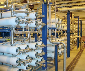
7. RO your boat. Two stages of reverse osmosis, with three trains per stage, follow the multimedia filter. Source: POWER magazine
RO-quality water is also stored in the service water tank for evaporative cooling of Redhawk’s gas turbines at a rate of 50 gpm each during the summer. This water also is used to backwash the MMF.
Plenty of instruments
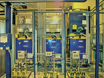
Boiler-quality water is derived from the RO unit’s effluent by a set of six parallel (and portable) mixed bed demineralizer trains. Each train consists of two bottles in series (the first called the “primary” and the second called the “polisher”), which means that 12 bottles can be in use at any particular time (Figure 8). Another set of six bottles is available on standby. Demineralized water from the trains is stored in a 1-million-gallon demineralizer storage tank that serves as the source of boiler water makeup.
8. Don’t drink this water. Portable demineralizer bottles are used to produce boiler-quality water. Source: POWER magazine
A number of design features protect against resistivity breakthroughs that could contaminate the contents of the demin water storage tank. Among them are resistivity sensors at the entry to each primary bottle, between each primary and polisher bottle, and at the exit of each polisher bottle of the six parallel trains. The alarm setpoint for each resistivity sensor is set at >12.5 MΩ/cm (<0.08 µS/cm conductivity). If an alarm sounds for the primary bottle of any train, that train’s primary bottle is removed, the polisher bottle is pushed upstream to become the new primary bottle, and a fresh bottle is moved into the polisher bottle position. This policy both affords excellent protection and stretches the Redhawk plant’s O&M dollar without compromising system performance.
A resistivity sensor also is installed at the trains’ outlet manifold, alongside a silica sensor with an alarm setting of 10 ppb. Downstream of these two sensors is a trip valve that serves as the demin storage tank’s final protective element. All of the tank’s instruments and HRSG boiler water-quality analyzers (Figure 9) are on a monthly preventive maintenance schedule.
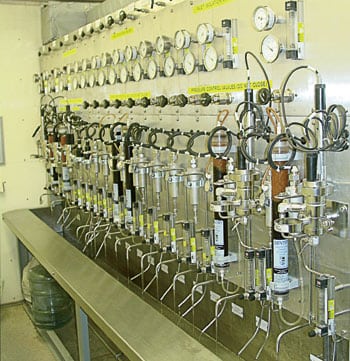
9. Panel of experts. All the conductivity and silica monitors in the reverse osmosis and demineralizer systems come to a single monitoring station. Also on the panel are the boiler water-quality analyzers. Source: POWER magazine
Waste not, want not
Redhawk’s water management systems are designed so that all boiler water makeup waste streams ultimately end up in the cooling tower basins. Having achieved that goal, the systems’ designers then had to tackle another tough problem: designing slipstreams to remove buildups of soluble and insoluble compounds in the basins at a rate sufficient to maintain the desired or permit-limited cycles (about 20) of the compounds’ concentration in the cooling towers.
The ZLD system uses a brine evaporation system (BES) to concentrate the soluble compounds in the blowdown stream until they precipitate. The waste stream from the BES is further concentrated in a brine crystallizer system (BCS) where precipitated material is removed by a centrifuge and trucked from the plant (bottom right of Figure 4). A big benefit of this approach is that it allows reuse of the evaporated and condensed water by the plant.
Evaporate, wash, recycle, repeat
10. Precipitation likely. The brine evaporation system concentrates soluble compounds in cooling tower blowdown, producing a distillate stream that can be reused in the plant. Source: POWER magazine
11. Spin, then dry. The brine evaporation system’s flow diagram. Source: Arizona Public Service
The blowdown entering the BES (Figures 10 and 11) has some alkalinity that must be removed to prevent calcium carbonate fouling of the system’s heat exchanger. Removing it is a three-step process entailing:
- Acidification. Metering sulfuric acid into the feed stream converts the carbonate and bicarbonate ions to CO2, which the deaerator can strip away.
- Preheating. This step kills two birds with one stone. It recovers heat from the outgoing process distillate steam and increases the concentration of dissolved CO2, making it easier to remove.
- Deaeration. Unvented CO2, if allowed to accumulate in the shell of the BES, can reduce some heat exchange surface and adversely affect the system’s performance. Under normal operating conditions, the level of CO2 exiting the deaerator is barely detectable.
The output of the BES carries 3.5% to 5.0% by weight of precipitated solids when the system is operating on spec. After most of the suspended solids are separated from the liquid product by a hydrocyclone (shown at the bottom right of Figure 13), some of the concentrated brine stream is sent to the seed recycle tank.
In the hydrocyclone, TDS and TSS (total suspended solids) are separated using centrifugal force to remove suspended solids from the liquid. The TSS is captured off the bottom of the hydrocyclone and goes to the seed recycle tank. The seed recycle tank is used to pump the TSS back to the BES for reuse. The TDS off the top of the hydrocyclone is routed to the crystallizer feed tank (CFT), which is described later.
Evaporated water vapor in the BES is washed of any entrained brine droplets before entering a compressor, where the vapor pressure is increased to the condensing temperature of the evaporator’s heater shell. This desuperheating reduces scaling of heat transfer surfaces and improves the overall heat transfer coefficient of the evaporator and associated heat transfer surfaces.
Because the total mass flow of vapor returned from the compressor will be greater than that required by the evaporator, the excess is vented from the evaporator shell through the deaerator. Most of the vapor is condensed on the shell side of the heating element, discharged as distillate, and recycled to the cooling tower sump.
Concentration of the brine feed in the evaporator precipitates calcium sulfate, which can cause scaling. However, although the rate of scaling is controlled by the equipment design and the slurry recirculation rate inside the evaporator, additional control is required to protect vessel and heat transfer surfaces.
The larger purpose of the seed recycle tank is to keep enough finely divided calcium sulfate in suspension to minimize scaling. In practice, the total surface area of the particles must be several orders of magnitude greater than the total surface area of the evaporator. The natural tendency of calcium sulfate to precipitate on itself significantly reduces precipitation on heat transfer surfaces. The initial feed is commercial gypsum or a hydrated form of calcium sulfate. The recycle of the seed increases growth sites for new crystal formation and keeps the process active
.
Solid performer
The crystallizer vapor body (CVB) uses a recirculation pump to send the concentrated slurry through the heater, which uses steam to condense the slurry on the heater’s shell side. Brine entering the CVB from the heater flash-boils and releases its heat as water vapor.
The vapor leaving the crystallizer is first cleaned by a chevron-type separator and then compressed by the crystallizer blower so it can be reused as a heat source by the heater to drive the evaporation in the CVB.
12. Liquid to solids. The brine crystallization system produces a waste product that can be landfilled. Source: POWER magazine

13. Condense, flash-boil, spin. Note in this flow diagram of the brine crystallization system how the compressor reuses heat that otherwise would be wasted. Source: Arizona Public Service
The CFT feeds the CVB, where crystallization of the waste stream actually takes place (Figures 12 and 13). As the TSS in the system concentrates, it is gravity-fed to a centrifuge, where the centrate is separated from the remaining solids (which range in wetness from moist to sand-like, depending on the season), which are trucked to a solid waste landfill (Figure 14). The centrate is returned to the CFT.
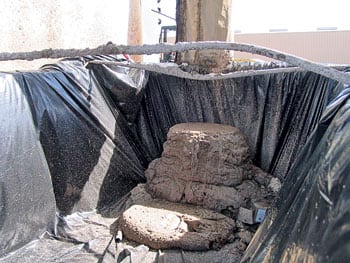
14. Have your cake. Solid wastes range in moisture content from wet to extremely dry, depending on the season. Source: POWER magazine
Theory to practice
Redhawk operators have been working for almost four years to perfect operation of the ZLD system. Along the way, there have been some successes and some “challenges.” The ZLD system works very well today, but getting to know the peculiarities of the system has taken some time. You can’t go to college and get a degree in ZLD—the only diploma available is from the school of hard knocks.
The Redhawk staff has had much success operating a ZLD system and has elected to share their collective experiences with the industry and those considering similar systems. Here are 10 prescriptive pointers that will either help you operate your existing system more efficiently or make the selection of a system for your new plant less problematic down the road.
1. Include the vapor washer option. A large number of brine concentrators have mesh pads inside the structure just above the sump area. Accessing these pads for cleaning is often difficult. In addition, particulates can sometimes make it past the mesh pads and cause scaling problems on the evaporator fan blades. At Redhawk, evaporated water vapor from the brine concentrator passes through the vapor washer (VW) on its way to the evaporator fan. This provides added fan protection.
Redhawk’s VW is a co-current scrubber design (shown on the right of Figure 10). Water from the VW sump is sprayed into the incoming vapor parallel to the vapor flow. As the large spray droplets combine with the smaller entrained droplets, even larger, coalesced droplets form. As the vapor leaves the VW downcomer, a 180-degree turn causes most of the droplets to leave the vapor steam and fall to the sump area of the VW. The cleansed vapor then flows through a layer of mesh (which removes almost all of the remaining entrained material), leaves the vapor washer, and heads over to the suction of the evaporator fan/compressor. Access to the mesh pads for cleaning in a stand-alone vessel is much easier than it is in a brine concentrator design with self-contained mesh pads.
2. Consider evaporator maintenance. In Redhawk’s falling-film evaporator, two distribution plates sitting above 40-foot-long titanium tubes distribute the brine evenly down the tubes. During mechanical cleaning of the evaporator, these plates are unbolted and set aside to allow access for hydroblasting the tubes. In some other evaporator designs, distributor caps with two small holes distribute the brine down the tubes.
Our experience with the double distribution plate design is that it takes more effort to get to the tubes because the heavy plates must be removed. However, the double-perforated distribution plate design appears to be less prone to plugging with our type of water than the distributor cap design.
At another of our Arizona plants equipped with an evaporator with the distributor cap design we found a buildup of scale between the cap and the inner tube wall. We have experienced instances of through-wall pitting and/or corrosion of the tubes in these locations.
3. Upgrade your crystallizer blower instrumentation. Almost all crystallizer systems have a propensity for foaming due to the nature of the fine particles that develop over time in the system. The original design of Redhawk’s crystallizer blower included local pressure switches on the suction and discharge sides of the vessel. But because the switches were not sensitive enough to pick up small pressure changes, foaming occurred after large load swings. In the end, Redhawk replaced the original pressure switches with more-sensitive pressure transmitters and tied them into the plant’s distributed control system (DCS).
The upgrade enabled the protective trips on the blower to be set to respond to a foam carryover from the crystallizer vapor body. The pressure setpoint was increased from 0.5 to 2.5 psi for two reasons: because small operating pressure swings occur routinely and because the original setpoint could allow a swing into the negative range, creating a vacuum and carrying over foam into the blower. Prior to the upgrade, the blower had to be removed from service and rebuilt several times during the first 18 months of operation because the system response was slow. Finally, the liquor level in the crystallizer vapor body was lowered from 50% to 10%, lowering the foam level below the site glass and making visual inspection easier.
4. Optimize centrifuge performance. The original plant design called for a centrifugal feed pump to control flow from the crystallizer vapor body to the centrifuge. Several different pump designs were tried, but all failed due to the challenging operating environment caused by the boiling crystallizer liquor/salt slurry. The final solution was to remove the pump from the system and use a combination of crystallizer pressure and gravity to feed the crystallizer slurry to the centrifuge.
This solved the centrifuge feed problem but did not offer a method for metering the flow rate. The Redhawk centrifuge is rated for 25 gpm of 25% salt. The centrifuge had to be rebuilt on several occasions due to overfeed flowed by plugging. Plugging causes backup of the slurry, which eventually will find a path across the seals and into the oil system, destroying bearings in the process. The solution: a flow meter and control valve was placed in the feed line upstream of the centrifuge and an automated flushing system controlled by the DCS was installed to keep the centrifuge clean.
5. Test your solids. Redhawk’s operators perform an ASV (apparent settled volume) test twice per shift. In this test, a sample from the evaporator and crystallizer are collected in 1,000-ml graduated cylinders. After the samples are allowed to settle for 30 minutes, the ASV is determined by observing the change in volume between the liquids and solids. For example, in the evaporator there is one salt level. If the settled volume were at 100 ml, then the ASV would be reported as 100/1,000 (10%) or 10.
By experience, the ASV of the evaporator now is maintained in the 5 to 18 range. It is important not to go below 5 to maintain enough seed material to prevent scaling of the evaporator tubes. If the ASV is greater than 18, the evaporator recirculation pump draws too much current, causing an alarm.
ASV is measured at two levels in the crystallizer. The heavier material found at the lower level is called “the salt” or “unders.” The fluffy-looking upper level is called “the fines” or “uppers.” For example, if the fines were at the 800-ml mark and the salt were at the 100-ml mark, the operator would report the crystallizer ASV as “80 over 10.” Operators also perform TDS tests on the evaporator and crystallizer systems twice per shift. The evaporator TDS is maintained below 170,000 mg/l, and the crystallizer is maintained below 375,000 mg/l. It is important not to exceed these limits to avoid exceeding the boiling point rise for each system.
6. You may require a crystallizer purge stream. During the first year of ZLD system operation, the crystallizer system had to be shut down and drained when its performance couldn’t be maintained. The reason was a mystery for some time. Optimizing centrifuge performance (see tip #4) and making the unit more reliable was a big step in the right direction, because the more it ran the easier it was to stay ahead of solids buildup in the evaporator and crystallizer systems. Optimizing centrifuge performance alone, however, did not completely solve the problem.
One important point learned by the Redhawk plant staff while troubleshooting the system was that “the fines” level of the ASV could be misleading, because most centrifuges are set up to remove one type of particle-size range of solids. In our case, the centrifuge favors removal of salts but allows the fines to pass through the centrifuge in the centrate and back to the crystallizer feed tank. The fines then re-enter the crystallizer vapor body and continue in this loop until they build to an “uppers” ASV of 100%. This eventuality should be considered in your plant design.
At one point, a cation polymer was used to help remove the fines. But the problem remained because periodic shutdowns followed by a system drain were still required. A consultant studied the system for several months and concluded that a small portion of the black liquor could not be processed in the ZLD system. He concluded that a small purge of approximately 0.5 gpm from the system would be required to maintain the system solids-liquid balance. A purge line on the centrate return to the crystallizer feed tank was added to minimize the amount of solids contained in the purge (Figure 11). When the dissolved-solids level in the crystallizer and/or the foaming in the vapor body get too high, operators now perform a controlled purge of the system.
7. Plan for ZLD maintenance. Outage planning for the ZLD system has to be taken just as seriously as outage planning for the power blocks. The lead time for certain parts can be weeks or even months. Spare critical parts should be purchased and stored on-site. At Redhawk, a spare crystallizer blower, centrifuge, and evaporator fan blade wheel are kept on-site.
Redhawk plans for spring and fall outages so evaporator tubes, vapor washer mesh pads, and crystallizer heater tubes can be cleaned mechanically by pressure washers. The 400F-rated Teflon crystallizer mesh pads are replaced rather than cleaned. The plant has learned that by performing two mechanical cleanings per year, an expensive chemical cleaning can be avoided longer. Mechanical cleaning can be done for $15,000 to $25,000 per outage, whereas a single chemical cleanings may cost upward of $100,000, depending on the amount of metals in the waste cleaning solution and how that waste has to be processed.
8. Expect water quality changes by season. The constituents of makeup water change during the year, and Redhawk’s experience has been that the operating characteristics of the ZLD system are different in summer and winter. For example, total organic carbon can be much higher during summer months due to algae growth in the holding pond. What’s more, high total organic carbon levels appear to put more demand on the ZLD system. Finally, nitrates also vary seasonally and can increase the boiling point rise in the evaporator and crystallizer systems.
9. Consider adding a brine concentrator surge pond. Redhawk has a 28-acre-foot brine concentrator surge pond that provides for a week’s worth of storage of cooling tower blowdown during ZLD system outages. This pond gives the plant more flexibility than other ZLD plants without surge ponds.
10. Add a hydrocyclone on the seed recycle tank. At Redhawk, the evaporator blowdown is fed to a hydrocyclone which was installed atop the seed recycle tank. It is used to separate the TSS or “seed” from the TDS. If the amount of seed material becomes too high (as measured by the ASV test), operators open the hydrocyclone bypass valve to allow the TSS and TDS to be fed to the crystallizer feed tank. Like the brine concentrator surge pond, the hydrocyclone gives Redhawk added flexibility, in this case, in evaporator operations.