Proper Valve Selection Reduces Downtime, Increases Process Efficiency
Proper valve sizing and selection saves facilities money by improving plant uptime and decreasing maintenance costs. One way to improve the selection of valves for a particular application is to take advantage of valve manufacturers’ wealth of information and experience. Valve manufacturers can work with designers to gather all the necessary information to specify the best valve and size for their applications, thus preventing common, costly mistakes that can reduce process efficiency and increase process downtime.
Many customer quotation requests provide only the line size, pressure class rating, and valve type. A typical request might read: size 4, Class 900 globe valve. Though this may be enough information to produce a valve quote, it rarely is enough information to size the best valve from both a performance and cost perspective. A reputable and experienced valve manufacturer will want to know not only the size and pressure-class rating, but also the following:
-
Design pressure
-
Design temperature
-
Upstream operating pressure
-
Upstream operating temperature
-
Flow rate
-
Allowable pressure drop
-
Pipe size, schedule, and material
-
Media flowing through the valve
-
End connection type
-
Alternate operating conditions
For example, a butt-welded, stainless steel system used to transfer caustic fluids will require a significantly different valve construction than a flanged valve in a carbon steel pipe system throttling steam or water. A generic request for a size 4, Class 900 globe valve does not communicate this critical information to the valve manufacturer (Figure 1).
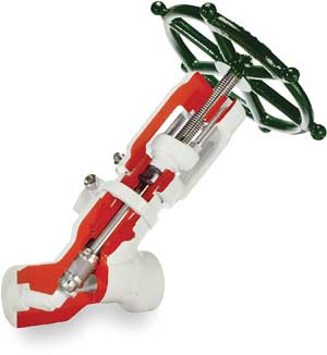
1. Globe varieties. Globe valves are distinguished by an element that closes parallel to the direction of flow. Available styles are T-pattern, angle, and Y-pattern (shown). Courtesy: Flowserve
Valve Selection: Isolation Valves
Gate and globe valves are used for initiating flow in a static line or for isolating flow in a dynamic line based on input from a handwheel or actuator. They are typically placed in a full open or full closed position, although most globe valves can be positioned partially open for rough throttling applications.
The throttling ability of a globe valve can be of significant interest for an end user, although it comes at a relatively higher price. A globe valve, size-for-size, will have a higher pressure drop than a gate valve. The straight-through design of a gate valve offers negligible pressure drop but is a poor choice for throttling applications (Figure 2).

2. Gate varieties. Gate valves are distinguished by an element that closes perpendicular to the direction of flow. Styles include wedge, flex wedge, double-disc, and split wedge (shown). Courtesy: Flowserve
It is not uncommon for a new design engineer to specify the requirement for a gate valve in a throttling application due to the lower pressure drop at the full open position. However, the closure element of a gate valve is prone to damaging vibration in partial stroke positions and is therefore not appropriate for throttling applications.
Sizing a gate or globe valve to match the line size of a system is usually a safe practice, but it may result in extra cost to the user. If the valve is allowed to develop a higher pressure drop than that provided by a line-sized valve, using a smaller valve could produce several benefits: The cost of the valve will be lower due to the smaller body size and, if the valve is to be operated with an electric, pneumatic, or hydraulic actuator, the size of the actuator will be smaller and thus less expensive.
Another consideration in choosing and sizing isolation valves is stroke time. On a size-for-size comparison, a globe valve will reach the full open position faster than a gate valve. A globe valve stroke length is approximately one-third of its nominal size, whereas a gate valve stroke length is approximately 100% of its nominal size. Standard actuation speeds for rotary, electric-actuated gate, and globe valves are 12 inches per minute for gate valves and 4 inches per minute for globe valves. Although this suggests an equal overall stroke time for both valve types, this is rarely true in application. Many gate valves need to stroke more than 100% of their nominal size, while many globe valves stroke under one-third of their nominal size to reach the full open position. Applications exist where gate and globe valves have very short stroke times — on the order of 3 to 10 seconds — but these valves rely on special, linear actuation instead of multi-turn actuation.
Globe valves used in throttling applications may need hardened seats, plugs, and stem and a body material that is more resistant to damaging erosion and cavitation. In these cases, a valve body material that is dissimilar to the pipe material is most likely appropriate; common valve body materials selected for erosion resistance in cavitation service include chromoly and stainless steel, which both possess a higher content of damage-resistant chromium.
If the piping system is constructed from carbon steel but the valve needs to be made with a different material, a full-service valve manufacturer will be able to weld carbon steel ends on the valve inlet and outlet (commonly called pipe pups or safe-ends). The post-weld heat treatment required after welding dissimilar metals is much easier to perform on the valve while it is still in the factory. When the valve is received by the end customer, the weld required to install the valve will be between similar materials, which eliminates the need to perform complicated post-weld heat treatment in the field.
In an effort to save money, design engineers commonly attempt to use a globe valve for an application that requires a control valve. Although control valves may use a globe valve design, they are in fact very different than globe valves designed for isolation services. Control valves are specifically designed to provide finite and stable flow control at mid-stoke positions, whereas a globe valve is only suited for rough adjustments to flow. Specifying a control valve for applications requiring stable flow control is worth the extra acquisition cost and can result in reduced maintenance and increased process efficiency.
Valve Selection: Control Valves
Control valves come in two predominant styles: globe and quarter-turn. Both styles feature characterized trim, which means the trim is designed to produce specific flow rates at specific opening positions. This characterized trim is what distinguishes globe control and quarter-turn control valves from conventional style valves, which are designed for quick opening and closing in isolation service (Figure 3).
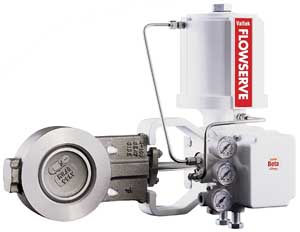
3. Similar style, different purpose. Globe control valves look very much like globe and quarter-turn isolation valves; however, they are specifically designed to work in partial stroke positions and with much finer flow control. Pneumatic actuators are the most common. Courtesy: Flowserve
Control valves are typically pneumatically operated and spend their entire operating life in a mid-stroke position. They can be designed to handle significant pressure drops across their seats with minimal velocity or cavitation damage.
Of all valves, control valves are the most complicated to size. In addition to the information required for isolation valves, the user must, at a minimum, specify the following for a control valve:
-
Process fluid and fluid properties such as vapor pressure, specific gravity, compressibility, etc.
-
Process temperature
-
Upstream and downstream pressure at all operating conditions
-
Upstream and downstream temperature at all operating conditions
-
Flow rate at all operating conditions
-
Available air pressure
-
Motive for actuation (pneumatic pressure, hydraulic pressure, electrical voltage)
-
Positioner signal/desired digital communications protocol
Much as with isolation valves, a control valve may need to be manufactured with a body material that is different from the pipe material.
Valve Selection: Quarter-Turn Valves
Quarter-turn valves are used for both isolation applications and control applications. About half of all control valves are quarter-turn valves. Typical quarter-turn valve styles include butterfly, plug, and ball. With the exception of butterfly valves, most quarter-turn valves are sized for small-bore lines and are used in lower-pressure class ratings, although some specialized valves are rated for high-pressure or large line size applications (Figure 4).
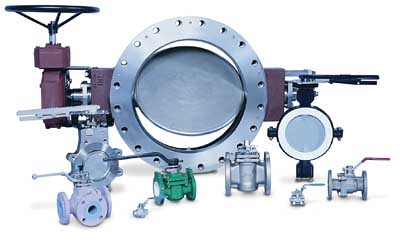
4. Quarter-turn valves. These are the predominant types of quarter-turn valves: butterfly, plug, and ball style. Ball isolation valves are much like gate valves in that they have negligible pressure drop and are not well suited for partial stroke applications. However, full open to close takes one-quarter of a turn, whereas a gate valve needs multiple turns of the handwheel. Special ball valve designs exist for partial stroke (throttling) applications. A butterfly valve is designed with a disc that rotates 90 degrees from full open to full close. The disc remains in the flow path at all times. These valves are generally used for systems with low pressure drops. Courtesy: Flowserve
Quarter-turn valves have three distinct advantages over multi-turn valves such as gate and globe valves:
-
Rotation location. The valve stem rotates in the packing box. With a multi-turn valve, the valve stem slides through the packing box, making it susceptible to dragging outside contaminants into the valve or dragging some of the valve contents to the local environment through the motion of the valve stem traveling through the packing. Though the magnitude of these contaminants either entering or exiting a rising stem packing box is very small, the phenomena might be a concern for some applications. Quarter-turn valves are less susceptible to this type of contamination.
-
Size and weight. Quarter-turn valves are typically lighter and occupy less space than their multi-turn counterparts. When space and weight become a concern, a quarter-turn valve is a better choice.
-
Faster movement. Quarter-turn valves can move from full open to full closed, or vice versa, faster than multi-turn designs. However, although quarter-turn valves stroke faster, the seats and trim elements for some designs are subject to shearing forces. For some designs, including certain ball valves, there is constant contact between the trim element and the seats. This can significantly increase the force required to operate these valves when there is a high pressure drop across the valve.
A common misapplication is the use of quarter-turn valves designed for isolation service in a throttling application. Although special designs exist for throttling, nonthrottling designs have poor control characteristics and are subject to severe damage.
Most quarter-turn valves are best suited for applications with high flow, low temperature, and low pressure drop. Outside of these conditions, a globe valve is most likely a better choice, particularly if cavitation or flashing conditions exist. One notable exception is high-pressure ball valves used for high-temperature and pressure isolation service.
Valve Selection: Check Valves
Check valves are unique because they operate passively. A check valve has two simple functions: stop the flow of fluid in the reverse direction and allow the flow of fluid in the proper direction. The control element of a check valve is most often a hinged disc or a floating plug (Figure 5). Some special-application check valves, such as inline check valves, may rely on a spring-loaded plug.

5. Check types. Check valves come in many types, including the tilting disc and lift check (shown). Courtesy: Flowserve
A special type of check valve is the stop check or non-return valve. This valve is simply a globe valve with the plug disconnected from the stem. When the handwheel is placed in the full open position, the valve acts like a piston check valve with the plug free to open in response to proper flow direction and to slide closed in response to reverse flow. With the handwheel fully closed, the valve acts as an isolation valve with the plug hardseated into the seat. This valve is subject to the same issues as both conventional check valves and globe valves.
Despite their seemingly simple function, check valves are prone to problems if they are incorrectly sized. If a line-sized check valve is used in a pipe with a relatively low flow rate, the disc or plug may not fully lift off the seat. This will cause the check valve element to move up and down (or rotate) due to flow turbulence and instability instead of remaining hardseated against the backstop. This movement results in premature wear of the sliding or rotating surfaces within the valve.
Common Control Valve Mistakes
Choosing the wrong valve for an application can negatively affect a plant’s operation and productivity. We end with some common control valve mistakes to avoid.
Expecting the control valve to be bubble-tight in the closed position. A control valve cannot seal as tightly as a true isolation valve. Many end users and engineers are tempted to specify a zero-leakage control valve in their attempt to use the valve for both control and isolation. Although this strategy may save money on paper by eliminating an isolation valve in-line with the control valve, it is impractical in application. A control valve is operated in a throttled position; accordingly, the seating surfaces are exposed to conditions that can cause local damage and poor sealing. Additionally, pneumatic actuators cannot produce the same amount of force that is necessary for tight sealing as a handwheel or electric actuator.
Specifying a control valve that is larger than the line size, or two sizes smaller than the line size. A valve is only as strong as the equivalent-sized pipe. For instance, a size 4-inch control valve in a 10-inch pipe will result in a weak point in the system and could be prone to structural failure. A 6-inch control valve in a 4-inch pipe will be too heavy for the pipe and will be incapable of producing the desired flow capacity or characteristic one would expect from a 6-inch valve in a 6-inch line.
Relying on a standard-trim control valve to handle the entire pressure drop in a pipe connecting a high-pressure system to a low-pressure system. Special trim is available on nearly all control valves that reduces the pressure in stages to mitigate cavitation damage. Though this capability results in a higher-cost valve, using a standard-trim control valve for such an application would be far more expensive in the long run due to frequent replacement of the standard valve trim.
Relying on a high-capacity control valve for start-up duties. Most control valves have a minimum and maximum flow rate that they can reliably control and moderate. Expecting a conventional globe control valve to reliably moderate flow at anything less than 10% of full open stroke is a recipe for frustration. Control valves exist that can moderate from nearly full/closed to full/open, but these are typically limited to quarter-turn control valves. These types of control valves are limited by temperature, pressure class rating or size, and their ability to operate effectively in severe service applications such as cavitation or flashing.
— Contributed by Tom Beaulieu, product manager, Flowserve Flow Control Division.