Proper Sizing of Steam Header Drains Prevents Water Induction
Steam turbines convert the thermal energy in motive steam to rotating mechanical energy, and the generator converts that energy into electrical power. One important requirement for safe and reliable operation is preventing water induction in the steam turbine and avoiding water hammer in the steam piping system. ASME standards present the design guidelines for removing moisture from steam lines; this article explains a practical design process.
The American Society of Mechanical Engineers’ (ASME’s) latest TDP-1 release presents well-proven design practices that prevent moisture from entering and damaging a steam turbine generator (STG). The water induction prevention standard (Recommended Practices for the Prevention of Water Damage to Steam Turbines Used for Electric Power Generation: Fossil-Fuel Plants, ASME TDP-1-2006) is based on the philosophy that “no single failure of equipment, device, signal, or loss of electrical power should result in water or cold steam entering the turbine.” A summary of the standard (“Preventing Turbine Water Damage: TDP-1 Updated”) was presented in the August 2009 issue of POWER and is available in the online archives.
Turbine water induction damages the steam turbine internals due to warping, cracking, or distortion of metal parts caused by severe quenching of the hot casing, rotor shaft, and blades. To provide moisture-free steam to the STG, the supply steam lines need to be adequately sloped and fitted with appropriately located drain lines capable of discharging any and all collected condensate (Figure 1). Once any condensate from these drain lines is collected, it is usually disposed of as flashed steam and/or condensate to the condenser or directed to an atmospheric vent. In the case of a condenser, the drain line is connected to a manifold, which collects drains from other locations as well. In case of an atmospheric vent, the drains may be directly connected to the vent or to a manifold connected to the vent.
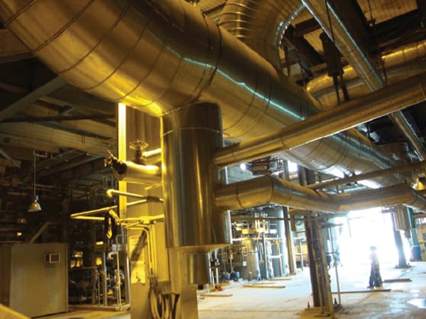 |
| 1. Collecting drains. Low points in main and reheat steam pipes are locations where any moisture in the pipe is collected and either vented to the atmosphere or drained, typically to the condenser. Courtesy: S. Zaheer Akhtar, PE |
Not directly discussed in the ASME standard is the fact that the presence of water in steam lines can also result in water hammer in the steam piping. Both water induction and water hammer phenomena can be very destructive to steam piping and equipment. Water hammer occurs when some of the steam condenses to water, forming a slug. Subsequent steam flow picks up and hurls this slug at high steam velocities, impacting the pipe bends/elbows and causing severe damage. The damage due to turbine water induction and water hammer in power plants is more common than you might imagine and has been experienced at many power plants. Fortunately, properly designed and well-maintained drain lines can mitigate water hammer damage by providing moisture-free steam.
Also not discussed in the ASME standard is a procedure for estimating the fluid parameters (such as flow, temperature, and pressure) as the fluid passes through the drain line and the downstream manifold/vent. This article presents a useful calculation procedure for sizing drain lines so that they do not restrict the necessary drain flows. Properly sized drains prevent a primary cause of both water induction and water hammer.
Steam Header Drain Control Logic
Steam header drains function in accordance with the control logic assigned to the power-operated valve in the drain line. Generally, the control logic requires the drain valve to remain open during the STG start-up period and close when the steam is superheated and/or when the STG has achieved a certain load. These drain valves can also be programmed to open or remain closed (depending on location and function) during an STG trip condition. Drains installed downstream of attemperators are usually fitted with a drain pot with level instrumentation and are used to collect and remove spray water leakage downstream of the attemperating station. Drain valves are provided with additional control logic to open in case of high water level in the drain pot.
The steam header drains are typically connected to a manifold that directs several drains from different locations to the condenser or the steam vent. The steam header drains can also be connected directly to a vent stack that is open to the atmosphere and fitted with a bottom drain for condensate removal. The maximum service conditions expected in the drain line and the downstream manifold/vent depend upon the control logic assigned to the drain valve and the steam header conditions when the drain valve goes to the “open” position. However, the worst case scenario usually occurs when the drain valve fails to open during full-load operation of the STG. In this situation, the drain line discharges superheated steam at full pressure through a vent to the atmosphere. The job of the plant designer is to ensure that, under these worst-case conditions, the drain line and the downstream manifold or vent are properly sized.
Drain Line Discharge Flow Capability
The first step in this calculation procedure is to find the drain line pressure drop. Because the pressure drop is generally greater than 40% of the inlet pressure, the modified Darcy’s formula for flow/pressure drop in compressible fluids applies. This formula enables the estimation of maximum discharge flow of steam through the drain line by considering the “choking” phenomena (the velocity of the steam is sonic) at the discharge line exit.
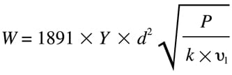
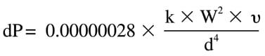
Recall that when the steam velocity is at sonic conditions or choked, an increase in upstream or a decrease in downstream pressure will not result in an increase in fluid flow. In this case, the choke point occurs as pressure falls off and velocity increases to sonic velocity at the downstream end of the pipe. The modified Darcy formula can be represented as follows, in equation [1]:
Where
W = steam flow rate (lb/hr)
Y = Net expansion factor (dimensionless) for compressible flow
d = Internal diameter of drain line (inches)
∆P = Pressure drop under choked conditions (psi)
υ1 = Specific volume at upstream conditions (ft3/lb)
k = Resistance factor (dimensionless) of the drain line, from the familiar Crane’s Flow of Fluids Through Valves, Fittings and Pipe
To illustrate the usefulness of this formula to the plant designer, equation [1] is plotted for steam flow from a typical steam header at four assumed upstream pressures (P1) through a nominal 2-inch drain line (schedule xs) under choked conditions (Figure 2). Note that for a given steam header pressure (P1) the rate of steam flow through the pipe reaches steady-state conditions for long pipes. In other words, the flow is choked.
Figure 2 also illustrates that the rate of steam flow through the drain line decreases with a decrease in upstream pressure (P1) and an increase in drain line Resistance Factor (k). The pressures assumed in the figure are typical of the range of values experienced in steam headers during start-up of the STG. Note that the relatively low pressure of 150 psia is typical for the reheat section during STG start, and this low pressure could limit steam flow through the drain line. Restricted steam flow through the drain line could, in turn, limit the heat-up rate of the steam header, thus increasing plant start-up time.
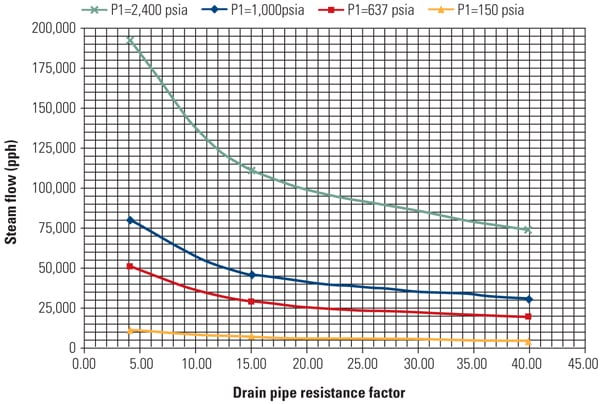 |
| 2. Calculating steam flow through drains. Steam flow through a 2-inch drain pipe is limited by the cross-sectional area and length of the pipe for different upstream pressures. Note that the horizontal line represents choked flow for the given steam pressure. Source: S. Zaheer Akhtar, PE |
Computing Vent Pressures
Atmospheric vents or drain manifolds are useful for collecting the discharge from several drain lines for disposal to the atmosphere and/or condenser. When discharging to the condenser, the manifold serves as a single connection to the condenser. Similarly, if the drain line is discharging to the atmosphere, it is usually connected to a large-diameter manifold joined to the vent stack or directly connected to the vent stack. The bottom of the vent stack is fitted with a drain line to discharge condensate collected at the bottom of the vent.
The flow through the vent or manifold is the sum of all incoming drain flows, and the steam properties in the vent/manifold can be evaluated as the weighted average of the incoming streams. The calculation for vent/manifold pressure should take into account the most severe situations, such as when one of the drains is inadvertently opened at full load or during an STG trip, when certain drains (usually from the cold reheat steam header) go to full open position with full operating pressure in the steam header.
You can calculate the vent header pressure of a vent discharging to atmosphere/condenser as follows:
- Set the header exit pressure (P2) initially at 15 psia (use condenser pressure in case of a manifold connected to a condenser).
- Using steam tables, and considering adiabatic expansion (∆H = 0), establish the exit temperature (T2) based on upstream steam header enthalpy (h1) and exit pressure (P2).
- Using P2 and exit temperature (T2), check the specific volume (υ2) from the steam tables.
- Now use P2 and v 2 to establish the sonic velocity (Vs), according to equation [2]:
![]()
Where
Vs = Sonic velocity (fps)
γ = Ratio of specific heats Cp/Cv (assume 1.3 for steam)
g = acceleration due to gravity (32.2 ft/sec2)
Also, evaluate the actual fluid velocity at P2 using equation [3], where As is the pipe cross-sectional area:
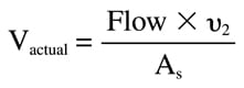
If Vactual exceeds the sonic velocity Vs, then increase the value of P2 until Vactual is equal to Vs. When the two velocities are equal, this condition represents choked flow conditions at the vent outlet. If Vactual does not exceed Vs, then P2 will remain at 15 psia and the flow is not choked.
Next, select the vent inlet pressure at any value higher than P’2 (say 50 psia) and iterate on dP until P’2– dP = P2. In this case the dP can be calculated based on Darcy’s formula with the specific volume calculated at the average of the fluid conditions found in the vent or manifold based on P’2 and P2, as calculated from equation [4]:
This computation, though tedious, is quite simple when programmed in a spreadsheet program such as Microsoft Excel. Figure 3 shows a summary of these computations for P’2 (vent inlet pressure, top) and P2 (vent outlet pressure, bottom) for the same steam header conditions and drain flow rates used to develop Figure 1.
As expected, the results of both sets of calculations illustrate that the vent inlet and vent outlet pressures decrease with increasing vent sizes. The results also show that the vent outlet starts choking (as evident by vent outlet pressure >15 psia, Figure 3, bottom) when the flow is increased.
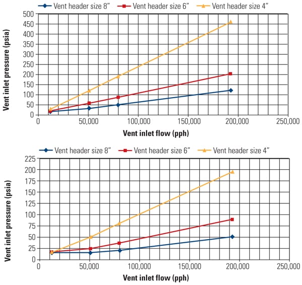 |
| 3. Calculating steam flow through vents. The steam flow rate through a vent for a given pipe size is determined by either the vent upstream pressure (top) or vent exit pressure (bottom) for a typical steam system. Nominal pipe sizes are shown in the figures. Source: S. Zaheer Akhtar, PE |
Calculating Condensate Flow Through Drain Lines
The computation of saturated condensate flow through drain lines is complicated, as the condensate continues to flash as pressure drop occurs in the drain line. The flashing water/vapor mixture continues to increase in specific volume and ultimately results in choked flow at a critical pressure (Pc). The mass flow calculation given by V. Ganapathy in Steam Plant Calculation Manual, 2nd ed., Chapter 3 as a solved example is iterative, which also lends itself to spreadsheet solutions. In addition to the equations cited above, the basic Bernoulli and sonic flow equations are required as part of the calculation procedure.
The solution process begins with an assumed value of Pc, and the mass flow rate is calculated using the basic Bernoulli equation and the sonic velocity using equation [2]. The assumed value for Pc (in atmospheres) is iterated until the mass flow rate calculated from the basic Bernoulli’s equation matches the mass flow rate calculated from the sonic velocity equation. The results are expected to facilitate the work of the plant designer by providing good estimates for two-phase discharge flow through the drain line.
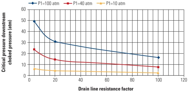 |
| 4. Calculating choked pressure. The downstream choked flow pressure can be determined using an iterative calculation methodology. The results for a nominal 2-inch drain line for three different upstream pressures (P1) are shown. Source: S. Zaheer Akhtar, PE |
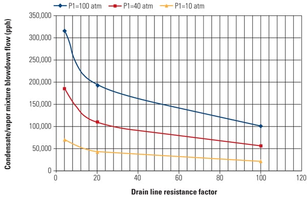 |
| 5. Calculating blowdown flow rate. The condensate/vapor mixture in blowdown flow is calculated through a 2-inch nominal pipe for typical upstream pressures (P1). This calculation procedure can be used by plant designers to determine the blowdown flow rate through a specific piping system for any given upstream pressure. Source: S. Zaheer Akhtar, PE |
Results from using this methodology were calculated for typical power plant steam header parameters illustrated in Figures 4 and 5. Figure 4 shows the final iterated critical pressure, which represents the mass flow rate where the basic Bernoulli equation and the sonic velocity equation agree. This mass flow rate was also evaluated for the same 2-inch drain used in a typical power plant (Figure 5). As expected, the mass flow rate decreases as the drain line resistance increases. To reduce drain line resistance, use a shorter line length or increase pipe size.
— Contributed by S. Zaheer Akhtar, PE ([email protected]), assistant chief, mechanical on assignment from Bechtel Power Corp. to Power Generation Engineering and Services Co. (PGESCo) in Cairo, Egypt. Soliman Abdel-Hamid ([email protected]) is chief engineer-mechanical at PGESCo. Our thanks to Dr. Ashraf Abdel-Moneim (PSEGCo) for his assistance in checking portions of our calculations.