Plant Automation Advancements: The Australian Experience
Many recent utility greenfield and rehabilitation power projects have incorporated plant automation, with the goal of reducing the number of operators needed. The essential design principle is to specify control systems and field devices that will achieve the desired operational regime. Here’s how it’s done “Down Under.”
The drive to reduce power utility operating costs includes reducing control room operator attendance requirements. Options to accomplish this goal range from simply centralizing the supervision of common plant functions to establishing fully unattended control rooms monitored by roving operators. However, such changes often add risk to plant reliability and increase operator stress levels.
Projects with successful low-attendance plant designs have effectively addressed the ergonomics issues, managed the transition process, and established the required levels of control automation. The plant designer must also consider plant protection, drive actuation, instrument redundancy, and alarm performance to match the target operation philosophy.
Automation in Australia Today
Many improvements in instrumentation, automation, and protection were introduced into new Australian power plants through the 1980s and early 1990s. In most cases, the changes were influenced by plant and control system suppliers from Japan and Europe, and were embraced and often improved upon by local engineering departments of the state-owned utilities. These included the use of high-pressure/low-pressure (HP/LP) bypass systems for fast startup, sliding pressure operation, islanding (operating independent of the grid), and unit coordinated control designs.
For example, at Stanwell Power Station in Queensland, beginning in the mid-90s, a new operational philosophy was introduced, enabled by increased levels of plant process protection, sequence automation, and instrument redundancy to maintain automatic operation. Total staff levels were around half that typically required, and a unique operating arrangement led to the introduction of “unattended operation” as normal practice. The station won an international award in 1995 for innovative operation and automation. Today, Stanwell operates four units nightly with only two roving operator/maintainers.
The outcomes at Stanwell subsequently influenced the automation requirements specified for both new plant and rehabilitation projects throughout Australia. These requirements included the introduction of single-pushbutton startup for supercritical coal-fired units, highly responsive plant performance, high-reliability control and protection, advanced alarm management, and provision for reduced and flexible attendance operation.
On many rehabilitation projects involving control system replacements, instrumentation and actuation levels were raised and control rooms were redesigned and, in some cases, centralized.
Unattended and Reduced Attendance Operation
“Unattended operation” describes the arrangement where all operators may leave the control room for plant monitoring or routine maintenance. A pocket pager, PDA, or tablet device is carried to receive any significant alarms and advice. Operator recall alarms and lights are also located around the plant and are activated if physical presence in the control room is required. The level of plant protection may be automatically raised in unattended mode (for example by activation of motor bearing temperature trips) until an operator returns to the control room.
From a physical perspective, the control room is unattended, but from a supervisory perspective, the operator (together with the protection system) remains in effective control of the unit and is at all times able to receive alarm information.
“Reduced attendance” operation may range from freeing one out of two operators to occasionally leave the control room, to having one operator supervise two or more units full time (while remaining in the control room). Though this arrangement does not usually involve portable operating facilities, the requirements for enhanced control, protection, alarming, and equipment and instrumentation reliability still exist. For example, if one operator is to attend to two units, the frequency of alarms doubles, so the acceptable frequency for each unit halves.
Control Design Principles
It is important to develop a clear philosophy of the role of the operator in reduced attendance situations and to ensure that appropriate design principles are established. This philosophy will define operator actions largely as responses and interventions, rather than as (the more traditional) monitoring, control, and protection. Consequently, the requirements for automatic sequencing, modulating control, alarming, and process protection are also affected.
Figure 1 represents the space of deviations of process variables away from normal in-service operation. The arrows identify the roles of different control, alarm, automatic trip, and operator actions under various disturbances. In this philosophy, minimal or no operator involvement is required under startup and normal operation. Alarms by definition will require some operator action, for which normal and protective control is inadequate.
 |
| 1. Bulls-eye. Hierarchy of control, alarming, and protection. Source: Provecta Process Automation |
Plant Protection and Override Actions. A raised level of plant self-protection is required if the operator is unavailable to immediately address urgent plant conditions that may require auxiliary plant trips, load reductions, or unit tripping. That is, decisions to take a plant out of service should be handed to the control system if the operator is not in the control room. The actual level of protection is related to the level of operator unavailability, which may range from a few minutes for dual-unit operation mode to much longer time periods for unattended modes.
However, simply increasing the number of plant trip signals can also increase the frequency of unnecessary or spurious trips. This situation must be managed by judicious use of field device redundancy, fail-safe/activate-to-trip design, and graded control responses. Additional protections are decided upon based on a failure-mode analysis and impact basis, applying to both generic plant types and specific plant incident scenarios. The integrity of increased levels of protection should be ensured by application of safety integrity level, or SIL, analysis and determination of instrument redundancy and trip circuit requirements.
If other actions can avoid a unit trip, these should also be taken by the control system. These may include additional load holds, unit runbacks, rundowns, and automatic starting of additional plant equipment, such as a feed pump.
Plant Sequence, Interlock, and Modulating Control. Reduced attendance operation generally requires high automation levels, particularly for unit startup and shutdown. Highly integrated sequence development for starting major systems or a complete unit startup requires a top-down design using a control hierarchy concept to ensure all process logic is properly and consistently managed. However, a bottom-up approach for fault analysis must also be included to ensure that the most common fault scenarios have been considered.
A hierarchical approach to sequence control design provides flexibility in start methods to allow the operator, for example, to choose full or partial sequence starts, to break out of and restart sequences, or to introduce hold points. Drive-level trip commands must also be input to the sequences as protection shutdowns to ensure the sequence remains in synch with the plant (Figure 2).
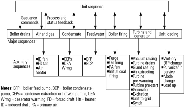 |
| 2. Orderly process. This is a typical boiler/turbine start sequence control hierarchy for automatic plant startup. Source: Provecta Process Automation |
Modulating control loops should be designed to remain on auto, where possible. This may include, for example, removing tripping to manual on dual-transmitter deviation, but always selecting the “safe side” signal rather than the average of the signals. In many cases, triplication will be required.
Alarm System Design. Operating four or more units in a single control room becomes very difficult if the alarms must be managed by only one or two operators.
The Engineering Equipment Materials and Users Association (EEMUA) is a key industry body that in 1999 developed guidelines for procedures and practices in alarm management. The publication has since been updated and has become an important reference for alarm design and management. The standard focuses on aspects of operations usability, safety of plant and personnel, engineering design, and performance monitoring. In 2009, the International Society of Automation (ISA) published its Standard 18.2, Management of Alarm Systems for the Process Industries, which also sets out comprehensive requirements for alarm systems design and implementation.
These guidelines have given rise to common usage of some reference points as limits of acceptability for alarm traffic:
- One alarm per 10 minutes on average.
- Ten alarms in 10 minutes following a plant upset.
It has been argued that these criteria are simplistic and inadequate. Nonetheless, in a one operator/two unit situation, each unit would be required to initiate only one alarm on average every 20 minutes—a challenging goal to reach.
Such a low alarm frequency has been attained at several plants in Australia through extensive engineering effort and ongoing review and management. Design principles used include ensuring that:
- Common design philosophies are implemented across the entire plant.
- All alarms from an out-of-service plant are blocked.
- All multiple alarms initiated directly from an event are rationalized to the root cause.
- Auxiliary plant trips are eliminated, except for the trip alarm and cause alarm.
- Transient alarms associated with load changes are revised or eliminated.
- Multiple process alarms from the same plant area, such as metal temperatures, are grouped.
- All alarms require an operator action; other events are redirected to appropriate alarm groups.
- Downstream (child) alarms are blocked (such as switchboard protection alarms).
Instrumentation Rationalization and Redundancy
Increased instrumentation redundancy, when correctly designed, can introduce a higher level of plant protection without increasing spurious trips due to instrument failure. Indeed, some of the most highly protected plants in Australia, far from being the most sensitive to tripping, have become among the most robust, with two stations holding records for the world’s longest running units without trips.
However, each plant designer must rationalize the level of automation that makes sense within that plant’s operating context. Table 1 is a guideline for the level of instrument redundancy in a control system retrofit project appropriate to the desired automation and operator attendance level.
 |
| Table 1. Instrument redundancy decisions guide for control systems replacement projects. Source: Provecta Process Automation |
Other Important Factors
There are many other factors to consider besides the control system when moving to an unattended or reduced attendance operation mode. A risk assessment involving parties from management, engineering, operations, and maintenance can identify important issues that might have been otherwise overlooked. Listed below are issues commonly identified during these team meetings that must be addressed prior to and during the transition.
Plant Reliability. The reliability of a plant can be given insufficient consideration during automation upgrades, and it is often not until the plant is operating in the new mode that previously managed problems become significant operational issues. In particular, the capacity to reduce alarm traffic and successfully deploy a more sensitive plant protection philosophy is highly plant dependent.
Operation and Maintenance (O&M) Practices and Skills. O&M practices usually need to be revised and skills enhanced to match the new requirements of any new operating regime. This may involve intensive training, culture change management, and role changes. Traditional responsibilities such as emergency coordination, safety isolation management, and routine testing may need to be transferred or shared with other work groups.
For control system replacement projects located on a brownfield site, involving operations staff during the control system design and testing phases often introduces the new system in a positive way.
Control Room Environment. The layout of the control room and desks should enable operation of multiple units by one operator while also allowing for multiple operators during contingencies. Provision should be included for large-screen displays to enable viewing of alarms and trends from a range of viewpoints, and the ability to operate, without ambiguity, different units from any station.
One possibility for control desk arrangement for dual-unit operation (one operator for two units) is illustrated in Figure 3.
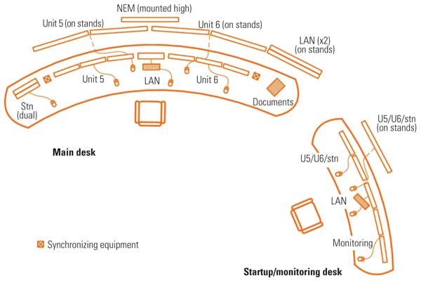 |
| 3. Elbow room. One possible control room desk layout for one operator supervising two units is shown. An additional operator would be assigned during unit restarts. Source: Provecta Process Automation |
Australian Plant Operations
A qualitative assessment of the factors affecting ease of operation of a particular utility, mapped against general groupings of operational arrangements, can provide an indication of what has been needed at the plant and control level to achieve a particular level of operator attendance.
Based on detailed experience with a number of power stations throughout Australia, we have developed an “operability index” to assist in the study of these relationships and to help generators better understand requirements for moving to new operational practices. The plants are all conventional drum or supercritical once-through units ranging in size from below 100 MW to around 700 MW and are fired by coal, oil, and/or gas. Table 2 is a sample of outcomes from this assessment process. Power plant names have been removed.
 |
| Table 2. A sample of the categories and scores for plant operability assessment. Source: Provecta Process Automation |
The criteria for this index include:
- Plant complexity
- Plant condition and reliability
- Protection system integrity
- Alarm system performance
- Level of sequence and modulating automation in the target operating conditions
- Fuel type(s)
- Operator panel arrangement and control room environment
Figure 4 plots each station’s operability index against its operation category. It is clear that lower attendance levels require higher operability, although there is quite a spread in the most common categories. The operation categories used in this assessment are:
- One operator per unit; operator remains in the control room.
- One operator per unit; one operator can leave the control room to attend to the plant.
- One operator per two units; backup operator is available when required.
- One operator per two units; operator can leave the control room.
- One operator per two or more units (or two units plus station); operator can leave the control room.
Any utility considering operational changes can plot its current position to assess the requirements for a successful transition. This may require additional expenditure on plant actuation, alarm management, or even improved routines for plant maintenance. For example, Station M in Figure 4 is currently undergoing an automation upgrade, which opens the possibility for moving from category 1 to category 3.
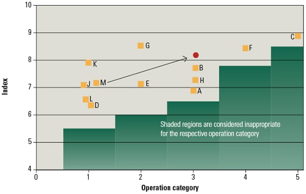 |
| 4. Identifying candidate plants. Operability index versus operation regime is mapped for a variety of power stations. Note that points within one category are separated horizontally only for clarity. Source: Provecta Process Automation |
Case Study: Station F
Station F is a midsize, supercritical, once-through plant. It utilizes roving operator/maintainers with a pocket paging alarm system for unattended mode. The plant has achieved:
- Very high ramp rates.
- Single-pushbutton hot and warm starts to full load.
- Fully automatic operation from 30% to 110% overload in automatic generation control (including automatic mill scheduling and feed heater removal for overload operation).
- Advanced modulating control design.
- Unit islanding.
- High levels of instrument redundancy and protection.
- Hot start times around 2.5 hours from first fire to full load.
Much of the Australian power industry has embraced high levels of automation and protection, which have enabled new coal-fired generating plants to start up with minimal operator actions—even to the point of enabling single-pushbutton starting and functioning in an “unattended” mode. These changes have not been at the expense of plant reliability or performance. Indeed, when properly engineered, the higher integrity levels of control and instrumentation systems that are needed to achieve these outcomes often improve plant operational performance.
— Don Parker ([email protected]) is principal engineer for Provecta Process Automation. This article was derived from a technical paper presented at the 2012 ISA POWID Symposium.