Microturbine Technology Matures
Microturbine technology has evolved from early systems of 30 kW to 70 kW to today’s systems, which can have individual ratings of 200 kW to 250 kW. Packages up to 1 MW are now available that can be assembled into multipac units for projects of 5 MW to 10 MW. These modern units are packaged with integrated digital protection, synchronization, and controls; they produce high combined heat and power efficiencies; and they are capable of using multiple fuels.
Microturbines are a relatively new technology for the generation of electric power. So, not surprisingly, questions are often raised by potential customers, engineering firms, original equipment manufacturers, and government agencies about how microturbines perform and how they differ from other more traditional forms of electric power generation. This article addresses those questions, describes the major features of microturbines, and gives examples of how they are used in real-world applications (Figure 1).
 |
| 1. Easy inspection. A 65-kW Capstone C65 microturbine equipped with integrated heat recovery is inspected by a technician. Courtesy: Capstone Turbine Corp. |
Typical Microturbine Construction
Microturbines are a simple form of gas turbine, usually featuring a radial compressor and turbine rotors and often using just one stage of each. They typically recover exhaust energy to preheat compressed inlet air, thereby increasing electrical efficiency compared with a simple-cycle machine. The air-to-air heat exchanger is termed a “recuperator,” and the entire system is typically called a recuperated cycle.
Figure 2 shows a cutaway view of a Capstone 65-kW microturbine illustrating how these major components are arranged in a commercial product. The assembly is often called a “turbogenerator,” as it includes all the microturbine components plus the generator. The single shaft of turbine, compressor, and generator rotates at high speed—96,000 rpm in the case of the Capstone C65 turbogenerator. Generator output is therefore high-frequency AC, which must be conditioned using power electronics to provide a useable 50 or 60 Hertz electrical output.
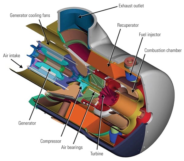 |
| 2. Inside view. This cutaway view of a Capstone C65 turbogenerator illustrates the arrangement of all the gas turbine components, including the generator. Ambient air is compressed in the compressor, fuel is burned in the combustor to raise the temperature of the compressed air, and the high-pressure hot gases expand through the radial turbine to produce shaft power for the generator. The recuperator recovers heat from the hot gases to heat the compressed air before entering the combustor to reduce the amount of fuel consumed, thereby increasing the thermal efficiency of the turbogenerator system. Source: Capstone Turbine Corp. |
Microturbines provide high electrical efficiency compared with traditional gas turbines in the same size class. The recuperator that recycles a portion of the exhaust energy back into the energy conversion process produces the efficiency advantage. Figure 3 illustrates the competitive offerings of several microturbine manufacturers plus selected larger gas turbines. Note that microturbines offer the highest electrical efficiency, up to about 5 MW, which is the size of the first traditional gas turbine offered in a recuperated model (Solar Tubines’ Mercury 50).
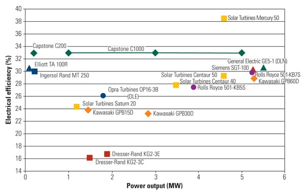 |
| 3. Efficiency contest. The electrical efficiency of the competitive offerings in the microturbine size range. Source: Capstone Turbine Corp. |
However, efficiencies in the high 20% to low 30% range are usually not sufficient to provide an attractive economic return on investment in commercial applications where conventional fuel is purchased and the resulting cost of generation must be compared with utility purchased power. The strength of the microturbine option lies with combined heat and power (CHP) or combined cooling, heat, and power (CCHP), where the clean exhaust heat can be recovered and productively used.
The primary value of any microturbine for most business customers is its ability to reduce the cost of energy. In addition to using standard financial analysis methods to evaluate a project, microturbines are often eligible for federal incentives when operating on a renewable fuel and a federal 10% investment tax credit that may be taken as an upfront grant. Many states also have rebate and incentive programs to stimulate the purchase of clean, efficient generation solutions.
Although an attractive payback on investment is usually necessary to generate serious customer interest, several market drivers help determine how rapidly microturbine technology is adopted, as explained below.
Microturbines Meet Low Emissions Limits. An increasing number of regulators around the world are adopting ultra-low-emissions levels similar to those of the California Air Resources Board (CARB). This means that other generation alternatives, such as reciprocating engine generators, often must add selective catalytic reduction systems. Several microturbine manufacturers meet the CARB requirements without active exhaust after-treatment, providing significant cost advantages to owners.
One of the benefits of microturbine technology is its capacity to achieve extremely low exhaust emissions levels. Continuous lean premix combustion provides low levels of oxides of nitrogen (NOx), carbon monoxide, and unburned hydrocarbons (often measured as volatile organic compounds).
As a useful point of comparison, natural gas–fired reciprocating engines produce NOx at a rate about half of the average utility-scale power generation system. The 65-kW Capstone C65 (whose heat rate is about 11,800 Btu/kWh LHV) produces NOx at a rate of approximately 9 ppmvd, a fraction of rate of a large natural gas–fired reciprocating generator set.
In sum, microturbines offer superior performance without the need for costly active exhaust cleanup. Emissions are a key reason why a major oil and gas company exploring large shale reserves recently ordered 18 low-emission C65 microturbines in August to provide prime power for its central processing facilities and metering sites in the Eagle Ford shale gas development in south Texas.
Microturbines Meet Tough Utility Interconnection Requirements. Some areas of the world limit grid connection of traditional synchronous generators due to their fault current contribution to an already stressed distribution system. Most microturbines use power electronics with digital processor controls. This approach allows integrating the unit’s protective relaying functions into the microturbine itself, including current limiting in the presence of a utility fault condition.
Most microturbines use power electronics to convert the high-frequency output from the generator to 50 or 60 Hertz 400V to 480V three-phase AC, which is useable by customers. The high-frequency AC from the turbogenerator first passes through an inverter and is converted to DC. From this internal DC bus, a second inverter stage creates suitable 50 or 60 Hertz AC. This output is filtered to meet the low harmonics requirements of IEEE 519.
An advantage of this type of microturbine technology is that the output inverter includes integrated protective relay functions, so little or no addition equipment is required to meet many local utility interconnection requirements.
Microturbines Make Integrated Systems Possible. Multiple units can be linked into a microgrid that offers many advantages for owners. (See “Microgrids Promise Improved Power Quality and Reliability,” June 2008 in the online archives at https://www.powermag.com.) A single power system controller can manage multiple engine packages to synchronize their voltage outputs, adjust their power outputs for maximum efficiency, and retain a spinning reserve so that the system can react to anticipated load changes. The result is a single “virtual” package that acts as a single system with unique efficiency and control characteristics.
An advantage of this integrated system is that power modules can be started or stopped as needed to maximize part-load efficiency. This feature can be valuable when system loads are expected to vary dramatically during operation or where the initial installation is based on potential future load growth. This type of system is also useful for utility substations to help manage peak loads. Figure 4 shows the part-load efficiency of a series of five 200-kW microturbine modules functioning in tandem compared to using a single, larger turbine. The area of the curve between the two part-load lines represents fuel savings.
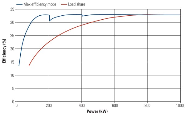 |
| 4. Practical part-load efficiency. This figure illustrates the part-load efficiency of a series of five 200-kW microturbine modules functioning in tandem compared with using a single, larger turbine. The area of the curve between the two part-load lines represents fuel savings. Source: Capstone Turbine Corp. |
The ability to automatically synchronize power output to an electric utility grid or between microturbines can also be integrated into the microturbine controls. This feature simplifies the coordination of multiple units and has allowed the packaging of multiple microturbine power modules into a single package.
Microturbines Provide a Secure Power Source. Microturbines are able to operate continuously for long periods with minimal outage time for maintenance. They are also highly reliable, making them a good choice for customers who need secure power with extremely high availability. Capstone has taken advantage of these characteristics, along with the capabilities of its power electronics, to create an integrated uninterruptible power supply (UPS) and power generation system called a “Hybrid UPS.”
The system consists of two separate inverters, called load control modules (LCM1 and LCM2). The LCM1 acts as a grid connect inverter, including the integrated protective relaying that most electric utilities require in order to allow a microturbine generator to be interconnected with their system. LCM1 is also bidirectional, allowing power flow either to or from the utility bus. The LCM2 acts as a stand-alone inverter, meaning that it is providing voltage to the critical loads regardless of what the utility bus voltage is doing. Internal to the Hybrid UPS system is a DC connection that ties LCM1 and LCM2 together, but it also allows power to come from the microturbine generator and an external battery storage system.
In the UPS mode of operation, power flows from the utility bus through LCM1 to the internal DC connection and then back out through LCM2 to power the critical loads. This is exactly as a traditional double-conversion UPS system would operate. However, the Hybrid UPS adds another mode of operation called “High Efficiency Mode.” In this mode, the microturbine generator is turned on and supplies power to the critical AC bus through LCM2. Typically, this microturbine will also be part of a CHP or CCHP system providing high-efficiency power that can reduce customer energy requirements. These systems achieve their highest efficiency, and therefore best economic payback, when they are following the thermal requirements of the CHP or CCHP system.
The Hybrid UPS design allows for thermal load following and does not require that the microturbine produce exactly the amount of power required by the critical load. This is because LCM1 allows power to flow out to the noncritical part of the distribution system or can pull power in from the utility as needed to match the critical load requirements.
The third mode is “Emergency Mode,” in which the microturbine generator and/or the external battery source can supply power to the critical load when utility power is unavailable. There is seamless transfer between all these modes so that critical loads do not experience voltage fluctuations that can impact sensitive data center or telecommunications equipment.
Recent Case Studies
Following are two examples of microturbine installations for the purposes of illustration. The first is a renewable fuel application using a single 200-kW microturbine. This system has been running for almost two years. The second is an application of twelve 65-kW Hybrid UPS microturbine systems installed at a university data center.
Wastewater Treatment Plant Installation. Until spring 2009, the biogas by-product flare that burned continuously above the plant figured prominently in the carbon footprint of a wastewater treatment center outside Cossato, Italy. The waste gas was considered a nuisance by-product of the treatment process (Figure 5).
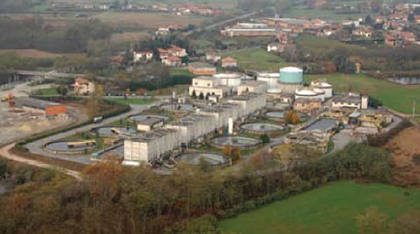 |
| 5. Recycling biogas. The Cossato Spolina wastewater treatment plant had flared the biogas produced by its digesters until a microturbine was installed that could use that fuel to produce electricity and thermal energy. Courtesy: Capstone Turbine Corp. |
Today, a single Capstone CR200 turbine provides all the electrical power needed at the treatment plant, along with heat to make the plant’s digesters work at optimum efficiency (Figure 6). This simple, elegant system likely will serve as a model for similar projects at wastewater treatment plants worldwide.
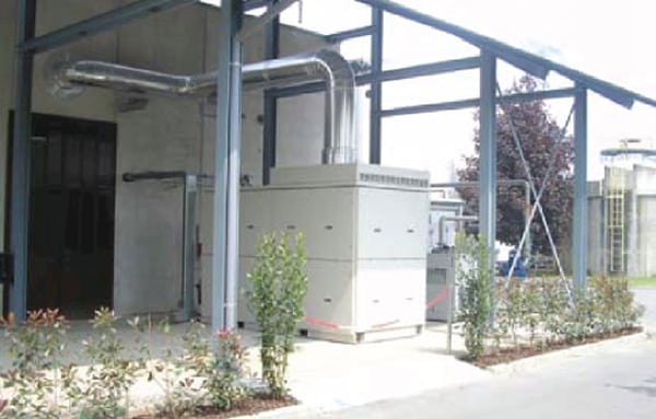 |
| 6. Closed system. The Capstone CR200 installed at the Cossato Spolina wastewater treatment plant burns waste biogas produced by the plant and now supplies all of the plant’s electricity needs. Thermal energy recovered from the microturbine is used to maintain the digester at the proper operating temperature. Courtesy: Capstone Turbine Corp. |
Numbers tell the story. First, the CR200 produces 1.7 million kWh annually, covering the plant’s electrical power needs with 2,600 cubic meters of biogas that was previously flared. Second, an external heat exchanger installed with the microturbine delivers another 2.3 million kWh of thermal energy to warm the digesters. Together, the combined heat and power produced cuts carbon dioxide emissions at the plant by 1.8 tons per year. A second unit is in development for this wastewater plant. With an 18-month payback, the design might revolutionize the way wastewater treatment centers approach combined heat and power generation.
Syracuse University Data Center. Twelve Capstone C65 Hybrid UPS microturbines recently were installed at a new data center at Syracuse University in New York State. The project was commissioned in December 2009. Syracuse University partnered with IBM and the New York State Energy Research and Development Authority (NYSERDA) to create a “Green Data Center” with the objective of reducing energy requirements by 50% compared with traditional data centers. Figure 7 shows the completed microturbine installation inside the data center. The data center totals 12,000 square feet, with about half of that representing the data center floor.
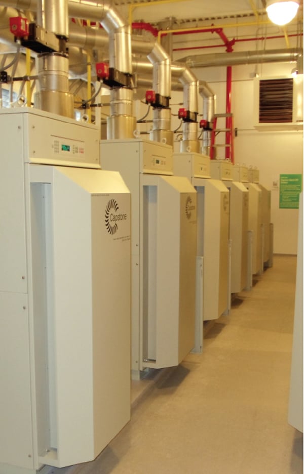 |
| 7. Cooling data. Twelve Capstone C65 Hybrid UPS microturbines equipped with heat recovery meet the electricity, heating, and cooling needs of the just-completed Syracuse University data center. Courtesy: Capstone Turbine Corp. |
This project used several novel approaches to designing a data center to reduce energy consumption, including:
- Hybrid UPS microturbines with advanced CCHP. The Capstone Hybrid UPS microturbines will operate on natural gas, and clean exhaust gas is used to drive both traditional hot water heat exchangers and double-effect absorption chillers to produce chilled water for cooling. The microturbines’ exhausts are diverted to one or both of these energy recovery systems, as needed by the facility. The result is high total system efficiency compared with the traditional approach of purchasing electricity from the local utility and satisfying building thermal demand with on-site gas-fired hot water heaters and absorption chillers. Another efficiency improvement is the reduced number of power conversions necessary when the microturbines are providing the critical load, compared to adding separate traditional double-conversion UPS systems.
- Chilled water data equipment cooling. IBM is providing its new Rear Door Heat eXchanger to keep the main data servers operating efficiently. Chilled water from the absorption system can be focused where it will be most effective, as opposed to using forced air cooling.
- DC power distribution. A portion of the critical load will be DC powered, again reducing the energy losses associated with multiple power conversions.
As part of the agreement between Syracuse University, IBM, and NYSERDA, the university will be monitoring performance of this facility against a comprehensive building model to both confirm energy savings and create the basis to predict the performance of future data centers built using these same efficiency improvements.
Integrating Solar Energy
In July, Capstone and HelioFocus demonstrated how solar energy can drive a microturbine. The demonstration was conducted with a Capstone C65 microturbine and a novel HelioFocus solar receiver on a fixed optical tower using heliostats at the Weizmann Institute in Rehovot, Israel. The HelioFocus Solar Concentrator focuses enough solar energy to provide heat to drive the microturbine. The system’s operation is similar to that of other concentrated solar power (CSP) projects, but, rather than heat a liquid, the solar collector superheats compressed air that is expanded in the turbine to produce power.
This renewable solution is said to offer high solar conversion efficiencies for systems in the 30 kW to 5 MW size range. The big advantage of this system design is that solar energy can power the turbines during the day, yet the turbines can also operate at night using natural gas or other renewable fuels, unlike traditional CSP systems.
— Stephen Gillette ([email protected]) is vice president, business development for Capstone Turbine Corp.