Microns Matter: Proper Design of Fogging Nozzles
Inlet fogging systems for combustion turbines achieve their effect at the molecular level: The cooling effect occurs by converting thousands of gallons of water into single evaporated molecules suspended in the air. The right fog pattern comes down to a matter of selecting the best nozzle design and proper placement in the inlet air stream.
Two Types of Nozzles
Two types of nozzles are commonly used for inlet fogging: impaction-pin nozzles and swirl-jet nozzles (Figure 3). Both designs operate on the principle of converting high water pressure into increased velocity as water passes through a tiny nozzle orifice. As water exits the nozzle orifice, it forms a conical sheet of water that gets ever thinner the farther it moves from the orifice. Surface tension causes the cone to first break down into fingers of water, and eventually, air instability breaks these fingers down into minute droplets for fast and efficient evaporation.
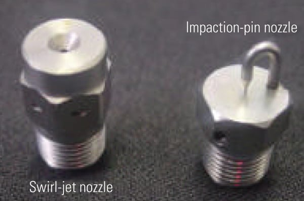 |
| 3. Two fog nozzle types. Two types of nozzles are in general use for gas turbine fogging applications: impaction-pin nozzles and swirl-jet nozzles; impaction-pin designs predominate. Courtesy: Mee Industries Inc. |
Although they operate on the same principles, the designs differ in how they create that cone of water, and this affects the size of droplets produced. Impaction-pin nozzles consist of a smooth, short, straight-through orifice with a specially engineered impaction pin in front of the orifice. A fine jet of water is emitted, which immediately strikes the pin, causing the water to form a cone of micro-fine particles. Swirl-jet nozzles, on the other hand, rely on the nozzle’s internal geometry to create the cone. An internal swirl chamber forces the water to exit the nozzle tangentially to the axis of the orifice, forming a hollow cone.
Both nozzle designs produce droplets in the sub-50 micron range, and either one will work for particular, noncritical applications. For example, when fogging nozzles are placed near the ceiling to cool or humidify a factory, greenhouse, warehouse, or restaurant, there is plenty of time for even the larger droplets to fully evaporate before falling to the floor. However, in higher precision applications, such as inside HVAC ducting or for turbine inlet cooling, droplet size is critical.
The Right Measurement
In discussing droplet size, it is vital to use the correct system of measurement. In evaluating a fogging system, droplets below a certain threshold are of no concern. Those that fall above the threshold, even if they are only a few, are what one needs to consider. With fogging systems, the droplets that fully evaporate as expected are not an issue, but the few larger ones that collect on duct walls and floors or enter the inlet of a compressor can potentially cause costly erosion and corrosion.
In evaluating fogging nozzles, therefore, measuring average droplet size is useless. If, for example, a volume of water is broken down into 1,000 10-micron droplets and a single 1,000-micron droplet, the average diameter of the droplets is 10.99 microns—too small to cause concern. However, because volume is the cube of the radius, that single large droplet has 1,000 times the mass of all of the smaller droplets combined. Even though the average droplet size is 10.99 microns, 99.9% of the water volume is being converted into 1,000-micron droplets. Rather than using averages, then, two other methods of measuring droplet size are useful in evaluating fogging nozzles: Sauter Mean Diameter (SMD or D32) and Dv90 (also known as Dv09).
The SMD is calculated by taking the sum of the cube of all diameters and dividing it by the sum of the square of all diameters. The SMD shows the average surface-to-volume ratio of the droplets, which is important because droplet evaporation only occurs at the surface. To maximize evaporation, the SMD should be as low as possible.
The other figure, Dv90, means that 90% of the volume of the liquid being sprayed consists of droplets at or below the Dv90 figure. A Dv90 of 20 microns would mean that 90% of the volume consists of droplets no larger than 20 microns. By selecting nozzles based on the right combination of SMD and Dv90 numbers, you can ensure that the water will evaporate at the most efficient rate and that very few large drops will fall out of the air stream and pool on duct surfaces or possibly find their way into the compressor.
With both swirl-jet and the impaction-pin designs, droplet size decreases as water pressure increases, up to a maximum of 137 barg (2,000 psig), producing plumes (Figure 4). The impaction-pin nozzles produced droplet sizes less than half the size of those produced by the swirl-jet nozzles, indicating that fog produced by impaction-pin nozzles will evaporate more completely and will contain fewer large droplets that can damage equipment.
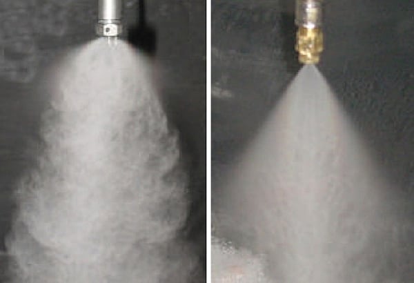 |
| 4. Perfect plumes. The plume characteristics of impaction-pin (left) and swirl-jet type nozzles (right) are shown at an operating pressure of 137 barg. The smoke-like nature of the impaction-pin nozzle is evident. The straight edge of the swirl-jet nozzle is indicative of the high momentum of the larger droplets, implying a much larger droplet size at the edges. Courtesy: Mee Industries Inc. |
Even Evaporation
Within the class of impaction-pin nozzles, there is still the issue of determining the type and size of nozzle to use. All impaction-pin nozzles are not the same. An ideal nozzle will produce an even plume so that the water will fully evaporate, producing the maximum amount of cooling with minimal excess water.
The first factor is the size of the orifice. Over the past 40 years, Mee Industries has evaluated a number of different orifice sizes and has found that a 152-micron (6 mil) opening works best for turbine cooling applications (Figure 5).
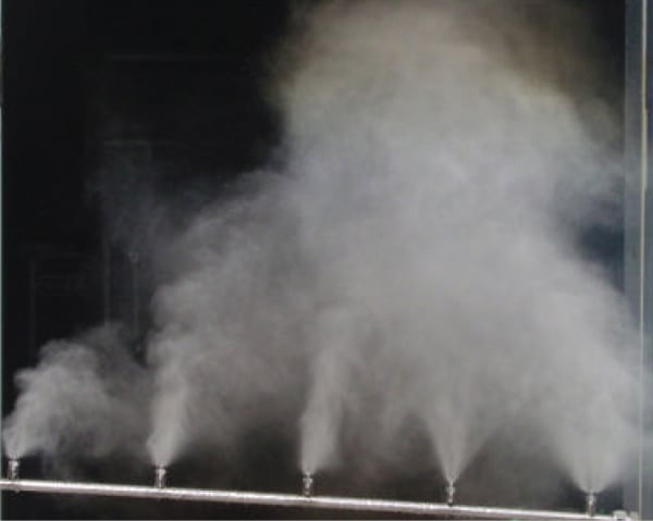 |
| 5. Different fog patterns. The fog pattern of various impaction-pin nozzles operating at 138 barg, from 457 micron (18 mils) orifice diameter (left) to 147 micron (5.8 mils, on the right) are demonstrated. The optimum 152 micron (6 mil) nozzle is in the center. Courtesy: Mee Industries Inc. |
The nozzle designs from different manufacturers also vary (Figure 6).
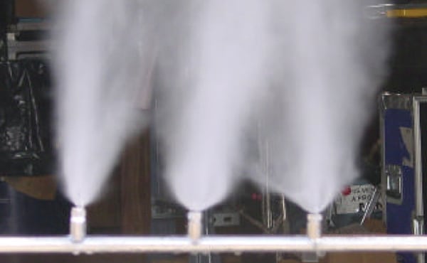 |
| 6. Each nozzle is unique. The visual plume shape of different makes of impaction-pin nozzles is shown at an operating pressure of 138 barg (2,000 psig). A Mee nozzle (152 micron orifice, 316 stainless steel construction) is in the center. Courtesy: Mee Industries Inc. |
Nozzles must be made of the right material; 316 stainless steel is recommended. The size and shape of the orifice and pin must stay at initial design parameters to continue making the ideal fog. Poor-quality metal will erode or corrode over time, resulting in excess water and oversized droplets.
Proper Placement
Once the right nozzles are selected, there is still the matter of nozzle placement to produce even evaporation of the water across the entire air stream. This is particularly important for turbine inlet cooling applications. Research has shown that there is little mixing of the inlet air. Nozzles that are not placed correctly can result in columns of air entering the turbine at different temperatures, humidity levels, and relative mass.
One big lesson learned by Mee Industries, with more than 800 installations of fog in gas turbines, is that the nozzles can’t just be spaced evenly in the inlet duct. Because the airflow velocity is not constant across the duct’s cross section, measurements should be taken to determine the actual speed at different locations. Computational fluid dynamic modeling can be employed to determine the best design to provide even cooling at different loads, ambient temperatures, and relative humidities.
A properly designed fogging array using the right type of nozzles produces the maximum amount of cooling, power boost, improvement in heat rate, and lowering of emissions. Just as important, it will achieve this without creating conditions that lead to unplanned down time or increases in maintenance expenses.
—Contributed by Kerry Rogers, chief engineer, research & development at Mee Industries.