Methanation of CO2: Storage of Renewable Energy in a Gas Distribution System
The ideal energy system of the future would be able to provide a constant supply of electricity based on renewable resources, without usage restrictions for the consumer. Unfortunately, many renewable energy sources, such as wind and solar, can only provide energy in an intermittent manner. To adjust the supply to the demand, the energy must be stored somehow.
Although electricity networks allow easy distribution of energy, the grid itself has no storage capacity. To store electricity, it usually has to be converted into other forms of energy. A variety of storage technologies currently exist:
- Electric energy (supercapacitors)
- Potential energy (pumped storage)
- Mechanical energy (compressed air reservoirs, flywheels)
- Electrochemical energy (batteries)
- Chemical energy (H2, syngas, methanol)
The capacities and discharge times of these storage systems vary (figure 1). Energy storage with flywheels and battery systems is currently very limited, and consequently they are primarily used for short- (<1 hour) or medium-term (<1 day) load balancing. For long-term storage and seasonal balancing, currently only chemical secondary energy carriers can be used. These include hydrogen and carbon-based fuels, which can be produced from various renewable energy sources.

Notes: CAES = compressed air energy storage, PHS = pumped hydro storage, SNG = substitute natural gas.
1. Discharge time and storage capacity of different electricity storage systems. Source: Sterner, 2009; Specht et al., 2010
The BMBF Project
As the German government has decided to phase out nuclear power, renewable energy sources will play an increasing role in the nation’s electricity supply. The increasing share of solar and wind power in the electrical network raises the problem of adjusting the fluctuating energy input to demand. In Germany, the potential for pumped storage hydropower generation is limited for geological reasons.
A promising possibility is to use the excess energy to manufacture methane from hydrogen and carbon dioxide. The electrical energy is used to produce hydrogen from water; carbon dioxide can be obtained from biomass gasification, cement plants, or carbon capture from coal-fired power plants. Additionally, the methanation process releases heat, which can be used in other processes. The generated methane can then be fed into the existing natural gas grid, which has a large storage capacity.
A concept for this possibility is being developed as part of a project promoted by the German Federal Ministry of Education and Research (BMBF, its acronym in German). In this project, Outotec is responsible for the methanation process. The project partners are Fraunhofer ISE, Engler-Bunte-Institut (KIT-EBI), the DVGW test laboratory at the Engler-Bunte-Institut of the Karlsruhe Institute of Technology (DVGW-EBI), IOLITEC, h-tec Wasserstoff-Energie-Systeme, and EnBW Trading.
Outotec’s work package has two parts: first to determine the optimal process conditions and catalysts, and second to work out and estimate costs based on the developed process design. The engineering component includes the process calculation (using Aspen Plus chemical process modeling software), plant design, and cost estimates for a suitable plant size.
Process Research
For the methanation process and plant design, different plant capacities (1,000 and 10,000 m³/h CH4) and feedstock mixtures (pure CO2 and a mixture of 50% CO2 and 50% CH4) are being considered. The dynamic operation of the plant is being tested with a part load from 30% to 100%. The plant uses a staged fixed-bed catalyst reactor, which is an in-house development based on knowledge obtained from sulfuric acid production plants.
Similar to SO2 oxidation as an interim step for sulfuric acid production, the methanation reaction also involves gaseous reactants and products:
4 H2 + CO2 D CH4 + 2 H2O ΔHr = −165 kJ/mol
Further similarities include the temperature range and the release of significant amounts of heat due to exothermic reactions. The heat of the methanation reaction leads to an increase of the gas temperature in the catalyst layer. On a large production scale, the reactor can be considered adiabatic. The conversion of CO2 is limited in accordance to the temperature equilibrium curve. To obtain the maximum CO2 conversion efficiency, the methanation is performed in several reactor stages where the gas is cooled before entering the next stage. Unlike the common sulfuric acid process, the methanation is designed to operate at elevated pressure (20 bar) to increase the yield of CH4.
Process calculations for 10,000 m³/h product gas (methane) with Aspen Plus and plant design were made (Figure 2). To achieve a high yield of methane, the process has four reaction stages arranged in series with gas intercoolers. The first step of the reaction takes place in the single fixed bed reactor (R1 in Figure 2). Stages 2 to 4 are included in reactor R2, which is the so-called stage reactor (reactor from sulfuric acid production).
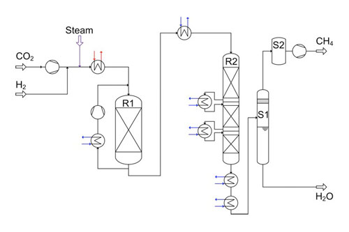
2. Process flow sheet for the 10 000 m³/h methanation design, with energy integration. Courtesy: Outotec
Hydrogen and steam are supplied from electrolysis with a pressure of 20 bar. The CO2 stream is pressurized to system pressure by a four-stage compressor and fed to the reactor R1 via a heat exchanger. From the reactor R1 outlet, a part of the product is fed back to the inlet in order to control the heat of reaction. The gas is fed to reactor R2 after cooling it to 300C. After each stage in reactor R2, the gas is cooled to the same temperature of 300C before entering the next stage. The byproduct water is removed in two stages, flash and molecular sieve (S1 and S2, respectively, in Figure 2).
An energy integration by means of a pinch analysis was performed for this process. Before energy integration almost 60 MW of process heat was available. After the energy integration more than 30 MW of process heat is used directly for heating up the feed gas to the reactor R1 and for producing electricity via a steam turbine. This electricity is used for the operation of compressors and other consumers. However, 27 MW of process heat are still available for further use (such as steam production or district heating).
Demonstration Facility
At the Outotec research center in Frankfurt, a catalyst test plant was commissioned to study the catalytic methanation of carbon dioxide and hydrogen (Figure 3). The capacity of this unit is 4 m³/h of gas flow (inlet), the operating pressure is 20 bar, and the inlet gas temperature is a maximum of 300C. Different fixed bed catalysts (these are commercially available for the methanation of carbon monoxide) will be tested for the methanation of CO2. The goal of these tests is to optimize the operating window of the commercial plant and to select the ideal catalyst for producing CH 4 from CO2.
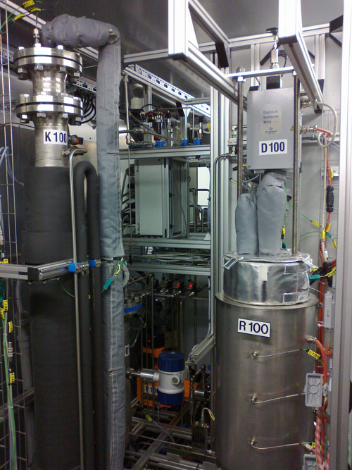
3. The catalyst test plant is shown here. Courtesy: Outotec
The process scheme is pictured in Figure 4. A mixture of feed gas is fed to the evaporator from gas cylinders. In the evaporator the feed gas is enriched with steam. Afterwards, the wetted gas is fed to the fixed bed reactor, where the catalyst is placed in a single layer between inert material layers for uniform gas distribution. The reactor is heated to minimize heat losses to achieve quasi-adiabatic conditions.
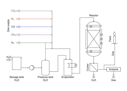
4. Process scheme of the catalyst test plant. Courtesy: Outotec
The produced gas is cooled to separate water from the gas. Afterwards, the gas is analyzed for its composition of CH4, H2, CO 2, and CO using an online analysis device and burned in a flare.
Several experiments were performed with one commercial catalyst for CO methanation at different inlet and maximum temperatures in the catalyst layer, as well as different gas hourly space velocity. The maximum temperature in the catalyst layer was controlled by adjusting the CH4 content in the reactor inlet gas stream. The catalyst height in the reactor, stoichiometric molar ratio between H2 and CO2 (H2 / CO 2 = 4) and addition of steam to prevent carbonizing of the catalyst (30% vol.) were constant. At these conditions a conversion of CO2 up to 70% was achieved.
Next steps will be the comparison of different catalysts and simulating the conditions in the different reactor stages of the production plant concept. Additionally, long-term tests will be conducted to observe the stability of the catalyst. The results will be incorporated in the simulation model of the production plant.
—Tanja Schaaf is senior R&D engineer, Jochen Grünig is R&D engineer, and Andreas Orth is vice president–energy for Outotec.