Making the grade with stainless steel tubing
Welding techniques have matured to the point where almost every austenitic, duplex, and full ferritic grade that is made in strip form can be manufactured into a tubular product by welding. Common grades, such as TP 304, TP 316, and their derivatives, are chemistry balanced to form a small amount of ferrite during solidification. This ferrite formation makes these grades particularly tolerant of variations in the welding process because the weld shrinkage during solidification is compensated for by the different densities of the two phases. This also allows for higher welding speeds.
The high quality of continuously cold rolled steel and coiled strip is one of the keys to getting repeatable high-quality welded tube. Currently, stainless steel coils are made as large as 50,000 pounds and 72 inches wide. Because of improvements in the rolling process, thickness tolerances are commonly held to 50% of that in ASTM specifications. Surface finishes are commonly 20 µinch Ra or better on both sides of the strip. (Ra is the surface roughness found as the arithmetic average deviation of the surface valleys and peaks expressed in micro inches.) The combination of high-quality surface and tight tolerance translates into a very concentric product with excellent surface quality on both the outer and inner diameter (OD and ID) of the tube.
Step 1: Slit the coils
The coils are slit in a continuous process to a width needed to make the desired tube hollow size (Figure 1). The slitting process is designed to develop a square edge that’s optimized for the square butt weld commonly used in manufacturing welded tubular products.
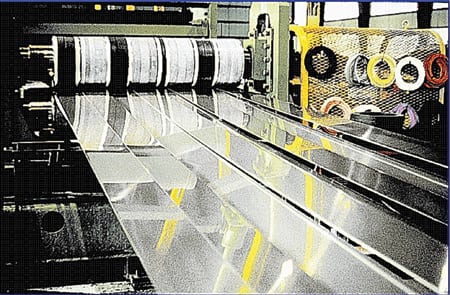
1. Cut stock to width. Stainless steel coils are split to the required width to begin the manufacturing process. Courtesy: Plymouth Tube
The most commonly ordered tubing specifications are SA 249 or SA 688 for austenitics, SA 268 or SA 803 for ferritics, and SA 789 for duplex grades. Ferritic grades that form martensite upon cooling are more of a challenge. The martensite is brittle and notch sensitive and may crack due to thermal stresses prior to the annealing operation. Some welded mills have developed proprietary processing and heat treatment methods that temper the martensite before it has a chance to crack.
Grades that do not form the compensating second phase during solidification, such as the higher alloyed austenitics and the full ferritics, require more care. This is typically provided by slowing welding speeds and using tooling just behind the weld melt pool that squeezes the pool at the same rate as the shrinkage occurs. This technique provides a high-integrity weld with no solidification shrinkage defects.
Step 2: Uncoil and roll form
An uncoiler (Figure 2) is located to provide precision alignment of the strip into the roll-forming operation. The strip is then roll formed using a series of polished rolls (Figure 3) in a progressive series (Figure 4) to provide the two strip edges to the welding location in the form of a square butt weld.

4. By the numbers. Forming a round tube from flat stock requires several gradual and precision rolling operations. Source: Plymouth Tube
The number of forming stations varies depending upon the design of the mill and the nature of the material being welded. There could be as few as six or as many as 14. Alignment of these stations and the uncoiler is critical to keep the weld seam perfectly centered under the welding head. Any misalignment can result in rolling of the tube and an off-seam condition in which the weld is not centered on the strip edges; in such cases, only partial penetration may result.
Step 3: Weld the strip edges
Three types of welding processes are commonly used for welding stainless steels:
- Tungsten inert gas (TIG) welding is the most commonly used process for stainless steel. During TIG welding, an arc is maintained between a shaped tungsten electrode and the tube. Inert gas is used to shield the molten puddle on both the OD and the ID. To provide good shape, a tube manufacturer may control the ID pressure by using a seal arrangement on the ID and controlling pressure. The TIG method provides for a high-quality, fairly wide weld with good penetration. The wide width offers two advantages: tolerance to minor rolling of the tube during the welding process and more weld reinforcement, which enables greater cold reduction during the in-line cold working operation.
- Plasma welding is used when greater penetration is needed on thicker walls. In this method, high-temperature plasma is used to provide the energy. Because of its high localized power, this process cannot be used on small-diameter tubing. Due to plasma’s greater penetration, welds using this technique are narrower than those created by TIG for the same thickness material.
- Laser welding of stainless steel tubing has become a reality with the advent of higher-power dependable lasers. Because of its high energy density, the laser produces the narrowest weld of the three methods. There has been extensive discussion about whether this is advantageous or detrimental. With the increased usage of laser welding, an interesting controversy has developed. The two acknowledged advantages are that it provides the highest welding speed and the least volume of segregated cast material. However, the very narrow weld has two disadvantages: increased potential for off-seam welding and little opportunity for weld reinforcement to take advantage of a bead-working operation.
All three of these techniques may be considered "fusion" methods because the weld becomes completely molten. Techniques that rely upon a "mushy" weld zone—such as high-frequency induction welding or resistance welding—do not work well with stainless steels because of their high chromium levels.
Virtually all welded tubing grades that have American Society of Mechanical Engineers (ASME) coverage are produced without the addition of filler metal because the weld is normally cold worked and heat treated prior to shipment, thus restoring the mechanical and corrosion-resistant properties of the original parent material. Trying to control the results of matching a filler metal chemistry to the base metal is more difficult than joining to the original parent metal and adds an additional level of complexity to the manufacturing process.
Step 4: Cold work the weld bead
The purpose of cold working is to assist with homogenizing the segregated as-cast structure. Cold working can be grouped into two categories: in-line bead working and full cross-sectional reduction. In-line bead reduction localizes cold working of the weld bead immediately following the welding operation and is performed directly in-line on the welding mill to ensure that the weld is maintained at a known and controlled position. Pressure is placed with tooling on the OD surface, reinforcing the ID with a hardened mandrel, and supporting the opposite side of the tube with a roll.
For stainless steel tubing, do not consider using a tube where polishing is used as a substitute for cold working. If seam alignment is not perfect, the polishing operation can selectively remove material from one side of the weld. This results in localized regions where the wall may fall below the minimum thickness of the specification (Figure 5). These locations are impossible to detect using normal testing techniques.

5. Not recommended. Polishing of welds instead of cold working can reduce the tube wall thickness below the minimum thickness specification. Courtesy: Plymouth Tube
Step 5: Cold draw to size
Welded tubing can be full-diameter cold worked by cold drawing (Figure 6). The process is capable of providing approximately half of the traditional roll-formed tolerance and an OD and ID surface finish in the 20 to 30 µinch Ra range. These tolerances are significantly tighter than seamless cold drawn tolerances because the welded hollow is very concentric.

6. Better tolerances. Stainless steel tubing can be cold worked into a specific diameter by cold drawing. Source: Plymouth Tube
In addition, stainless steel tubing can be cold drawn to raise the tensile and yield strength as much as three times the annealed value. However, in most heat exchanging applications, the benefit of cold working is not recognized, especially when ASME Code requirements are needed. The downside is that the extra manufacturing step will add to the product cost.
Step 6: Heat treat
For optimum corrosion resistance, all stainless steel alloys should be annealed after the welding and cold working operations. Doing so homogenizes the weld so that corrosion cells are not initiated in the segregated region. Tubes may be annealed one at a time in an in-line operation or in multiples in an off-line operation.
In-line heat treating. The most common method of annealing stainless steel tubing is in-line heat treating (Figure 7). In this process, the tube is heated with an induction coil to the desired temperature and then rapidly cooled with either water or a convective gas such as hydrogen. The heat treatment is performed in-line on the welding mill, usually immediately following the in-line cold working operation. Once the tube leaves the coil, the cooling process begins. Alloys such as the superferritic and superduplex alloys require a sufficient quench to prevent formation of detrimental second phases that can significantly reduce corrosion resistance (Figure 8).

8. Put out the fire. In-line quenching using water is typically used. Courtesy: Plymouth Tube
However, exposure to the air and water produces a scale on the tube surface (predominately chromium oxide) that must be chemically removed to ensure optimum corrosion resistance. The scale is usually porous and cracked and, therefore, not very protective. Beneath this scale is a region of chromium depletion that has inferior corrosion resistance. It is very important that this chromium-depleted layer be removed. Mechanical polishing may re-embed these chromium-depleted layers in the surface, having little beneficial effect. The only sure way to completely remove all depleted material is to use a chemical process. This is commonly accomplished using nitric acid or citric acid solutions.
A chemical method has some additional benefits for tubing. It can act as a 100% corrosion test of the tubing, especially if the process is performed before the final eddy current test. The acid will aggressively attack any sensitized areas or any inhomogeneities such as manganese sulfide inclusions exposed during prior processing. When an attacked area is eddy current tested, the alarm sounds and the tube is rejected.
Off-line heat treating. Alloys selected for specific applications can be continuously off-line annealed in a separate furnace. The additional annealing furnace hold time, typically in the 5- to 10-minute range, results in greater homogeneity and corrosion resistance. This is especially important for alloys with higher nickel and molybdenum concentrations. The welds for these alloys normally have more segregation, and longer diffusion times are needed for homogenization. Today’s high natural gas costs also make this process more expensive.
A bright annealing process is one in which a reducing gas such as hydrogen is used to create a reducing atmosphere that minimizes the formation of oxides. Because the surface of a bright-annealed tube does not develop a thick scale, the final tube surface finishes may be smoother. Bright annealing is only effective when the annealing temperature is above approximately 1,850F. When bright annealing is used, water quenching is not an option because the water causes the formation of a scale on the surface. Therefore, bright annealing quench rates may not be sufficient for some alloys.
Step 7: Straighten the tubes
Tubes may need additional straightening, sizing, and cutting operations after in-line or furnace annealing.
Step 8: Nondestructive testing
The completed tube must now successfully undergo a series of nondestructive testing (NDT) before it completes the manufacturing cycle. These include nondestructive electric (NDE) and pressure tests.
NDE testing. Two types of NDE tests are commonly used for stainless steel tubing: eddy current testing (ET) and ultrasonic testing (UT). ET is the standard test used for almost all stainless steel tubing. The method utilizes a full-encircling, differential coil that is most sensitive to sharp abrupt defects but not very sensitive to long gradual imperfections that bridge both sections of the differential coil. The amplitude of the signal from the imperfection is directly related to its abruptness. ET is fast and inexpensive, but OD defects tend to be more easily found than ID defects.
UT tests send a sound wave through the wall of the tube and then listen for an echo that is caused by a reflection from a defect. UT testing is sensitive to longitudinal straight defects such as cracks and incomplete welds but is slower and more expensive.
Pressure testing. Three kinds of pressure testing are commonly used on welded heat exchanger tubing: air-under-water testing, pressure differential testing, and hydrostatic testing.
The air-under-water testing method is performed by placing air-pressurized tubes in a well-lit tank of water while an operator walks the length of the tank looking for bubbles. Using test pressures of 150 to 250 psi, weepers as small as 0.002 inch can be routinely detected. Because of its low cost and high sensitivity, this is the most common pressure test used for welded heat exchanger tubing.
The pressure differential testing method became a production reality with the development of high-sensitivity electronic pressure sensors. The test is performed by pressurizing two tubes to the same pressure, closing off the pressure source, and monitoring the differential pressure between the two tubes. If the differential exceeds a predetermined limit, an alarm sounds. Currently, it is commonly used for testing welded titanium tubing.
The traditional hydrostatic testing method is being phased out because it is three orders of magnitude less sensitive than air-under-water testing. It is only used when required by a customer specification.
Step 9: Mill quality testing
Reputable tube mills use a combination of visual inspection, in-process eddy current testing, and manipulation (destructive) samples to continuously monitor the quality of the weld. Manipulation tests are designed to specifically test the ductility of the weld in various directions. For example, the reverse flatten test was developed to test transverse weld ductility on the ID surface; the flange test is a flaring operation to test for longitudinal weld ductility, primarily on the ID surface; and a tensile test determines longitudinal weld ductility. Each of these test methods is defined by applicable ASTM specifications.
Corrosion tests may also be performed on stainless steel samples, although they are not required by the majority of ASTM/ASME specifications. For example, a weld decay test will detect the presence of residual ferrite in a weld during solidification in primarily the 304 and 316 family of stainless steels. Boiling hydrochloric acid readily attacks the ferrite and, if present in the weld, will cause thinning of the weld at a much faster rate than the base metal. For a properly annealed weld, the ratio should be 1.00 or less.
Intergranular tests are designed to detect sensitization from slow cooling rates, insufficient annealing, or carbon and nitrogen contamination. They are normally called for to check if an alloy is "solution annealed"— a term most often applied to dissolving chromium carbides, which ensure that chromium is available to keep the stainless "stainless." These tests may not be meaningful for determining whether an alloy is suitable for an application and cannot determine if a weld is adequately homogenized for optimum corrosion resistance.
Final thoughts
When ordering stainless steel tubing, remember that merely ordering to an ASTM/ASME specification does not guarantee a good tube, whether it is seamless or welded. In general, ASTM/ASME specifications have minimum requirements that may not be sufficient for a specific application. Specification NDE test requirements are minimums that may not detect flaws that could cause problems in your specific application, and a single NDE test is not sensitive to all defects.
Our experience is that an eddy current test and an air-under-water test combination is cost-effective for finding the majority of defects that would cause future problems in service. Also, because most ASTM/ASME specifications do not require a corrosion test, consider adding one to your specification.
Realize that ASTM/ASME specifications are necessarily broad and open to a wide range of interpretations. Your expectations may not match what the supplier can supply.
—Daniel S. Janikowski ([email protected]) is corporate technical sales manager of Plymouth Tube. Ron Roth ([email protected]) is quality assurance manager of the West Monroe Plant of Plymouth Tube.