Load Cycling and Boiler Metals: How to Save Your Power Plant
As many coal-fired power plants designed for baseload service are asked to cycle, unforeseen stresses have been introduced to boiler pressure parts. Understanding the effects and implementing mitigation strategies could prevent premature component failure and keep facilities operating reliably.
On August 3, 2015, the U.S. Environmental Protection Agency finalized the Clean Power Plan, which calls for cuts in carbon pollution from existing power plants. This rule, coupled with low natural gas prices, could result in natural gas–fired facilities being used more frequently for baseload power and coal-fired plants being cycled, more than ever before, to meet grid requirements.
The majority of coal-fired units were designed and constructed as baseload units, without any anticipation of significant load changes. But combustion turbines and heat recovery steam generators offer higher thermal efficiencies (about 60%) than coal-fired boilers (the best steam plants may operate at a maximum efficiency of about 40%), which is also contributing to a change in dispatch tendencies.
Although coal-fired power plants are still in high demand, alternative sources are very attractive from an environmental point of view. Increasing variable renewable energy resources, such as solar and wind power, are placing additional pressure on coal-fired plants to load follow. However, load cycling in coal-fired plants causes negative long-term and short-term effects on equipment reliability and availability.
Load Cycling and Its Effects
Load cycling may include low-load conditions, hot startup, warm startup, and/or cold startup. Just as the term suggests, a low-load condition occurs when output is reduced and the unit is operated at a minimum load without being shut down. When a unit is cycled on and off daily, it usually undergoes a hot startup. Warm startups generally occur in units that operate for four to five days continuously and then shut down during weekends, while a cold startup follows an extended maintenance shutdown (usually the plant will have implemented a layup procedure for these lengthy upkeep periods).
Following are the most common undesirable effects of these sorts of cycling operations.
Creep Fatigue. Utility boilers are constructed using different materials and thicknesses. These materials expand and contract at different rates. In addition to creep damage, high-temperature components, such as superheaters and reheaters, experience thermal and mechanical fatigue. The cumulative effect is known as creep fatigue.
The resulting damage is much more severe than standalone creep or fatigue damage. Under cyclic loading, tube-to-header welds develop cracking due to a combination of fatigue stresses and hoop stresses. Fatigue stresses can result from relative movement between the components, specifically during warm-up or cool-down, or when load changes occur due to transient stresses. Fatigue stresses can also be present as a result of inadequate tube leg flexibility, defective supports/attachments, or rigid attachments on the pressure parts.
Ligament Cracking. Individual high-temperature superheat (SH) and reheat (RH) tubes may operate at different temperatures because of variations in heat distribution, slagging, fouling, and misalignment. Therefore, steam enters into the header at different temperatures.
Load cycling exacerbates the temperature difference between the individual tubes, because the firing rate is adjusted during load changes to maintain pressure and temperature. During load increase, the boiler is temporarily overfired, and the condition reverses when load is reduced. This causes transient thermal shocks to the header, resulting in ligament cracking.
High-Temperature Circuit Thermal Fatigue. In addition to these thermal stresses, the external stresses associated with header expansion and contraction can cause damage to cycling units, resulting in fatigue cracks at the attachments. An additional fatigue component can exist wherever components are joined via welding, because different parts expand and contract at different rates. Although the fatigue component is within the endurance limit, it will affect the creep properties of the components.
Over-Tempering. Creep-strength-enhanced ferritic steels (CSEFs), like T91 and T23, are very popular in modern power plants because they offer higher allowable stresses and superior creep properties than their ancestor grade steels, such as T22 and T11. However, there are some inherent long-term maintenance issues with the CSEF steels. The use of CSEFs in heavy-cycling units, specifically in reheat circuits, significantly affects the superior properties obtained through precise heat treatment, resulting in premature failures.
Dissimilar-Metal Welds. Dissimilar-metal welds (DMWs) are very frequently used in high-temperature circuits to facilitate material transitions. Load swings produce significant transient thermal and differential stresses on the DMWs. These welds are not only subjected to creep but also are susceptible to creep fatigue failure. Load cycling significantly reduces the useful life of a DMW.
Condensate in Low Points. Condensate usually collects in the remote sections of SH and RH circuits, resulting in two major issues: thermal fatigue and short-term overheating. The temperature difference that exists between the headers and steam can produce thermal fatigue cracking and ligament cracking. Warm startups produce significant thermal fatigue damage because the temperature difference is usually higher.
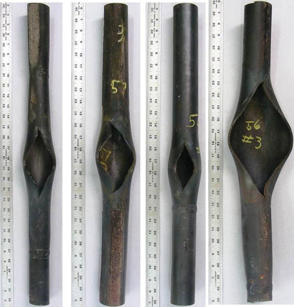
Rapid startup conditions may lead to short-term overheating failures, because condensate in system low points can cause increased metal temperatures downstream (Figure 1). The tensile strength of the steel decreases significantly once it is beyond design temperatures. Also, rapid startups and shutdowns, as well as load changes, can cause exfoliation of the inner diameter oxide scale. If the exfoliation is excessive, it may lead to pluggage of bends or erosion damage in the turbine.
|
| 1. Condensate in loops. This image shows several secondary superheater tubes that failed due to short-term overheating after only eight months of service. Courtesy: David N. French Metallurgists |
Low-Temperature Circuit Thermal Fatigue. In low-temperature regions of the boiler, load cycling also causes thermal fatigue cracking in economizer inlet headers or tubes, lower furnace wall tubes or headers, and steam drum internals. This fatigue cracking primarily occurs from the ingress of relatively colder water into hot boiler components or vice versa.
Corrosion Fatigue. Load cycling exacerbates corrosion fatigue on waterwall tubes because the differential stresses on waterwall tubes are higher during startups and load swings. Corrosion fatigue is not only a reliability issue, but it also is a safety concern because failures usually occur on the cold side of the boiler.
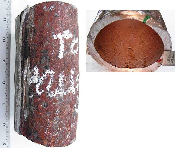
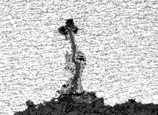
Conditions necessary for corrosion fatigue to occur include either having the boiler water oxygen concentration too high or the pH outside of the control range at the same time that stresses are high enough to break the magnetite layer (Figure 2). Corrosion fatigue occurs when operating or residual stresses break the protective magnetite (Fe3O4) layer, exposing the bare steel to the corrosive environment (Figure 3). These stresses are highest during transient periods.
|
| 2. Corrosion fatigue. This cutaway view shows a tube that experienced corrosion fatigue in the transition bend near the lower slope of a plant that cycled daily. Courtesy: David N. French Metallurgists |
|
| 3. Taking a closer look. This microscopic view shows a tube surface that has begun to crack as a result of corrosion fatigue. Courtesy: David N. French Metallurgists |
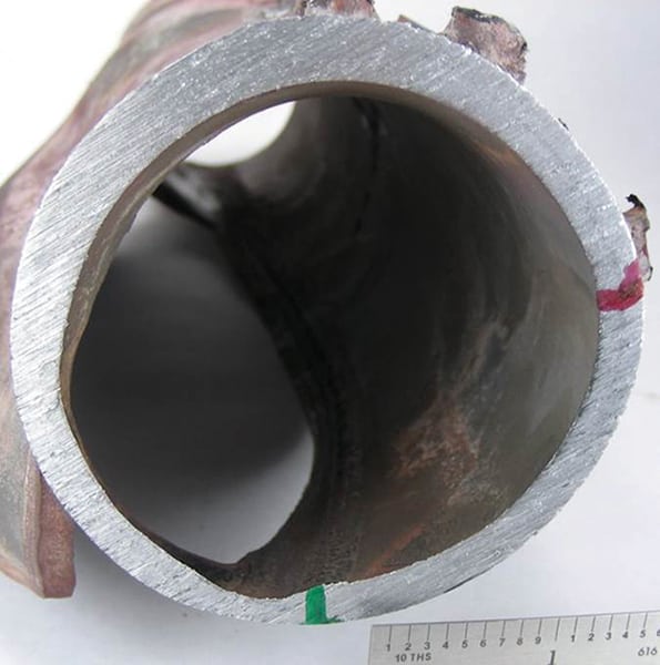
Caustic Gouging. Caustic gouging is a well-known issue in natural circulation units, specifically during low-load conditions. In natural circulation units, the coolant flow is biased to certain tubes because it operates on the density difference between the hot and cold fluids. Low-load conditions and load swings play a major role in caustic gouging because constantly changing conditions result in repetitive upsets to coolant flow. The flow upsets cause caustic to concentrate at the edges of steam bubbles. Caustic concentrations remove the protective layer of iron oxide, resulting in tube wastage (Figure 4).
|
| 4. Caustic gouging. This cutaway view shows a tube that experienced caustic attack in a cyclone inlet roof tube. The plant commenced load cycling about one year prior to this failure. Courtesy: David N. French Metallurgists |
Phosphate Hideout. Phosphate hideout, one of several forms of underdeposit corrosion, usually occurs when units are operating with phosphate-based treatment. Phosphate hideout causes ionic phosphate to disappear or absorb during high-heat-input conditions, but it returns or dissolves into boiler water when the heat input is reduced. Phosphate hideout promotes acid phosphate corrosion. Hideout becomes evident during load swings or startups while changing heat input. Dirty boilers are susceptible to phosphate hideout and acid phosphate corrosion.
Mitigation Strategies
There will always be some adverse effects on equipment reliability due to a low-load condition, hot startup, warm startup, or cold startup. Each of these conditions will affect the integrity of pressure parts one way or another. It has been observed across the board that warm startups cause the most damage to equipment, because the temperature difference is higher and there is greater susceptibility to air in-leakage than what is found during other cycling conditions.
Following are some useful strategies for mitigating equipment damage.
Add More Tube Flexibility. Fatigue stresses often occur as a result of inadequate tube leg flexibility between tube penetrations and the header, and also from rigid attachments on the tube. More flexibility and better attachment design will reduce the fatigue stresses. Sometimes header relocation may be required to provide more flexibility.
Use Slip-Type Attachments. Many older units were designed with rigid attachments. Slip-type attachments should be used in place of rigid attachments to accommodate differential thermal expansion.
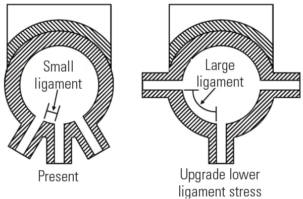
Redesign for Symmetrical and Widely Spaced Tube Penetrations. Several older plants were designed with closely spaced, unsymmetrical tube penetrations, which are susceptible to ligament cracking. It is well known that evenly spaced, larger ligaments are less susceptible to creep fatigue damage (Figure 5).
|
| 5. Bigger is better. Larger ligaments are less susceptible to creep fatigue damage. Source: David N. French Metallurgists |
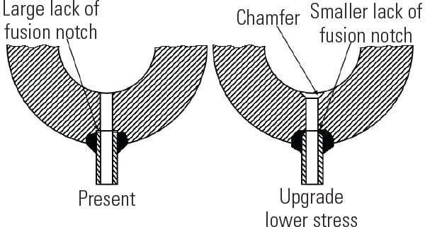
Redesign of tube-hole penetrations and tube-to-header weld configuration, especially eliminating the lack-of-fusion notch at the end of the tube penetration, can also increase creep fatigue resistance. The inclusion of a smooth chamfer at the inner diameter of the header bore hole reduces stress concentration (Figure 6), improving creep fatigue resistance.
|
| 6. Design changes. Elimination of the lack-of-fusion notch at the end of tube penetrations and including a smooth chamfer at the inner diameter of the header bore hole can improve creep fatigue resistance. Source: David N. French Metallurgists |
Make Periodic Inspections. The majority of piping-related problems are associated with hangers and support systems. Good attachment design is vital to minimizing creep fatigue. Periodically inspecting attachments and correcting deficiencies will reduce fatigue-related issues. Terminations of attachments should taper to the surface to reduce localized stress concentrations. Lack of penetration in attachment welds can result in hot spots where heat is unable to effectively dissipate or can increase stress concentrations. Good weld design and adherence to welding procedures is essential.
Lower Ramp Rates. Transient stresses due to load cycling affect the useful life of a DMW. Transient stresses can be reduced with slower startups.
Use Nickel-Based Filler Metals. A DMW can be made with or without filler metal, which will have a finite life. DMWs made with EPRI P87 or Inconel filler metal are expected to have a longer life than those without filler metals. A DMW made using nickel-based filler metal lessens the effects of the thermal expansion differences between stainless steel and ferritic steel.
Relocate DMWs. Stresses and temperatures are the critical factors in the lifespan of a DMW; performance can be improved by controlling these factors. The weld joint can be relocated to a position where it is exposed to lower temperatures. Frequent inspection and maintenance of tube hangers, supports, and spacers can be performed to reduce secondary loads.
Bake Tubes. Condensate in high-temperature circuits creates major problems during startup periods. The tubes should be baked for long enough to evaporate the condensate before increasing the heat input. Reduce the thermal gradient between the fluid and metal during startup periods. Although load cycling plays a major role in thermal fatigue, once the component reaches equilibrium, thermal fatigue will not be a significant factor.
Use Rifled Tubing. The use of rifled tubing in areas susceptible to underdeposit corrosion can provide better flow mixing to avoid potential corrosion issues. Load cycling significantly increases the susceptibility of waterwall tubes to corrosion fatigue. Fast startups increase transient stresses because different parts expand and contract at different rates, breaking protective oxides and exposing bare tubes to the corrosive environment.
Improve Welding Techniques. Pad welds should be avoided in regions susceptible to corrosion fatigue. The residual stresses from welding exacerbate corrosion fatigue. Additionally, poor weld profiles should be eliminated to reduce stress concentration. Lack of penetration in attachment welds can increase metal temperatures and stress concentration.
Maintain Proper Water Chemistry. It is critical to ensure that water chemistry is within range for pH and oxygen content, especially during startups or load shifts, to reduce the risk of corrosion fatigue. Boiler cleanliness must be maintained to reduce the risk associated with phosphate hideout. Use trisodium phosphates in place of mono- or disodium phosphates to bump phosphate readings. The addition of trisodium phosphates does not cause acid phosphate corrosion, but the addition of mono- and disodium phosphates can promote acid phosphate corrosion.
Avoid heavy blowdowns, which will significantly affect sodium phosphate ratios and aggravate the situation in units susceptible to acid phosphate corrosion. Perform periodic deposit weight density testing to know how dirty the boiler is. Boiler cleanliness will significantly reduce a majority of waterside issues. ■
—Rama S. Koripelli, PhD ([email protected]) is technical director for David N. French Metallurgists