Lamar Repowering Project’s creative melding of old and new wins Marmaduke Award

The ultimate power plant maintenance effort is a repowering project. This year’s Marmaduke Award winner demonstrates that sometimes the most creative solutions to repowering projects can be achieved by small generators. But there was nothing small about the scope of work undertaken by the Arkansas River Power Authority (ARPA) and Lamar Light and Power (LL&P). What’s more, the service they provide is no small thing to those they serve.
Small is beautiful
There are more than 2,900 public power systems and rural electric cooperatives in the U.S. serving about 27% of the nation’s electric customers, according to the American Public Power Association. Public power is transmitted in every state except Hawaii, so chances are you or your neighbor enjoys electricity service from a locally owned and operated power provider. If so, you also enjoy rates that are an average of almost 15% less than those charged by the nation’s 217 investor-owned utilities.
Colorado has an interesting blend of power providers: Investor-owned utilities account for 55% of energy sales in the state, rural electric cooperatives provide 28%, and publicly owned utilities provide the remaining 17%. The common challenge facing these providers is that demand is expected to grow almost 60% in the next 17 years, according to the state’s public utility commission. How to build more capacity in an environmentally responsible manner while keeping a lid on mounting capital costs weighs on the mind of every generator. Colorado does have one advantage few other states enjoy: moderate electric rates compared to the national average, because 80% of its energy is produced from coal.
The common thread among small Colorado municipal utilities—most formed years ago to supply power and water to the state’s 30 million acres of farmland—is that they are ill-equipped to be competitive in today’s highly interconnected, mega-utility business environment. Their answer was to form confederations that share the output of their generating stations in order to cope with rising energy demand and wield more purchasing power in wholesale power markets. Many own gas- or oil-fired facilities that are uneconomic now that fuel costs are high compared to the cost of wholesale power available to municipalities.
ARPA, located in southeastern Colorado, was formed in 1979 by seven municipalities: Holly, Springfield, La Junta, Trinidad, Lamar, and Las Animas in Colorado and Raton, New Mexico (Figure 1). Each member municipality continues to own and operate its electric system and distributes electric power within its service area but commits to purchase all its needed wholesale energy from ARPA. ARPA is able to contract for the additional wholesale power needs of its members from a variety sources and has funded construction of various plants (mostly gas-fired) for its member over the past 25 years.
1. Small but significant generator. The Arkansas River Power Authority represents seven municipalities. Lamar Light and Power contributed a significant portion of ARPA’s baseload generation until Unit 6 was placed into long-term storage in 2003. Source: POWER
Tightening power supplies
By 2003, ARPA was purchasing wholesale power primarily through a power contract with Tri-State Generation and Transmission and received a federal hydropower allocation from the Western Area Power Administration (WAPA). However, the agreement was not renewed by Tri-State when it expired on Sept. 30, 2004. ARPA then entered into a “bridge purchase” arrangement with the Municipal Energy Agency of Nebraska (MEAN) for supplemental power needs from October 1, 2004, through September 30, 2007, with mutually agreed-upon six-month extensions covering ARPA power needs to date.
ARPA’s power purchases equal 337,000 MWh annually, to serve a total peak demand of around 80 MW. Load growth has averaged about 0.4% since 2001 and is expected to continue on that pace through 2014. An integrated resource plan was commissioned by ARPA in late 2004 to evaluate power supply options and recommend the best long-term approach for providing reliable baseload generation and stable rates to its members.
The impending baseload capacity deficit was severe when resource planning was limited to a series of six-month power contracts. But so were increasing natural gas prices and the expensive replacement power purchases ARPA was obliged to make for its members. ARPA investigated other long-term wholesale power purchase options to replace the six-month MEAN contracts, but none was available given the state’s growing appetite for power and the limited transmission into the state.
By late October 2005, ARPA had refined its planning assumptions and capital cost estimates and balanced them against the risks of relying on purchase power contracts in the future. The solution selected was to repower the existing LL&P Unit 6 with a coal-fired boiler and recycle the turbine side of the LL&P retired plant in conjunction with installing a new steam turbine to produce approximately 38.5 MW net of baseload generation. Some might dispute the “repowering” description of the project, preferring instead to call it a “refueling” project. We’ll get into the interesting technical details in a moment.
By 2007, 61.5% of ARPA’s power requirements were purchased from MEAN, 24.3% from WAPA, and 5.6% from Xcel Energy. When the repowering project begins commercial operation, the MEAN and Xcel Energy purchases will be replaced.
LL&P: The linchpin
Other ARPA power generating assets include a 7.5-MW gas-fired turbine, 5.5 MW of relatively new oil-fired generation, plus a single 5-MW coal plant owned by Raton that is slated for retirement. ARPA also owns two and LL&P owns three 1.5-MW wind turbines that were added to the system a few years ago and continue to operate reliably, and at 4.4 cents per kWh, very economically. But LL&P contributed the majority of the baseload energy used by APRA from its gas/oil-fired 25-MW Unit 6 steam turbine (built in 1972) until the 1990s; it continued to provide a significant share until mid-2003, when it was placed into long-term storage because of rising fuel costs.
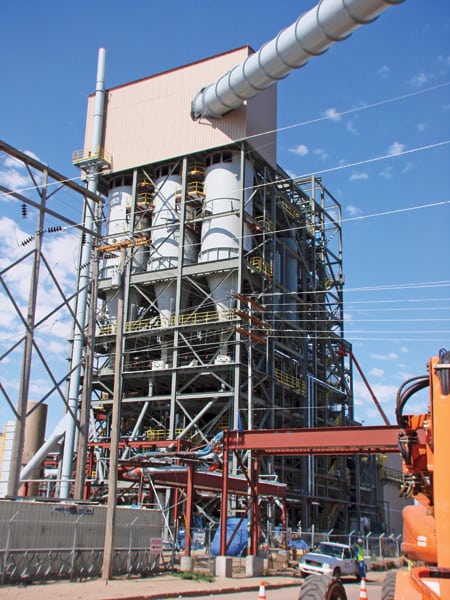
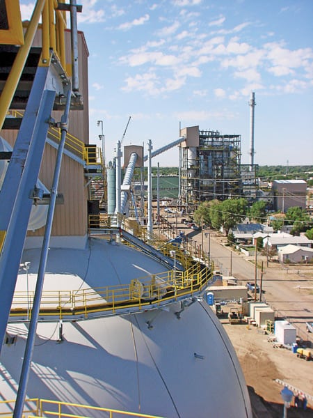
The Repowering Project, or Unit 8, is a joint undertaking between ARPA, LL&P, and the City of Lamar. ARPA issued Colorado Power Revenue Improvement bonds to finance the estimated $120 million plant construction cost and is the plant owner on paper. LL&P committed its existing facilities and provided the site adjacent to the project to construct Unit 8’s new coal-fired steam generator and a new 18-MW steam turbine that will work in tandem with the existing Unit 6 steam turbine (Figure 2). ARPA calls Unit 6 “dedicated facilities” even though LL&P retains ownership. In addition, LL&P will be the operating agent for the facility.
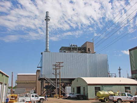
2. Squeeze job. Unit 8 was constructed adjacent to the Unit 6 building (far right) on open land. The 227-foot stack is a new downtown Lamar landmark that’s located just a block east of Main Street. The SPX air-cooled condenser is the elevated aluminum building in the foreground. The new turbine building is the brown building directly behind the condenser. Source: POWER
Rick Rigel, LL&P’s superintendent and ARPA’s Unit 8 project manager, emphasized that the project’s main purpose was to supply all the baseload power needs of the seven ARPA members for many years to come. Rigel pointed out that ARPA expects rates will rise in the short term as wholesale rates will be based on this single, higher-priced plant, but rates will stabilize in the future. Even so, rates are expected to be immediately competitive with market rates at 7.75 cents/kWh when Unit 8 enters service this summer, perhaps about the time you are reading this article. These rates are well worth the wait when WAPA’s spot purchase rates are predicted to be as high as 12.4 cents per kWh this summer.
Siamese twin turbines
The design of Unit 8 illustrates how creative plant designers can be when given a blank sheet of paper.
A four-story power house built in 1972 encloses the existing Unit 6 steam turbine, condenser, and auxiliaries. The control room of the old plant was reused with a distributed control system (DCS) to supervise operation of the new power plant, but the old panel board from the Unit 6 steam turbine was kept in service because it was too expensive to replace, and the system remains functional.
As was typical when it was built, the Unit 6 control room is just off the enclosed turbine deck, about 150 feet from the edge of the new project site. The rest of the building encloses the Unit 6 boiler and other power generating equipment retired in-place years earlier.
A new building was constructed adjacent to the Unit 6 turbine building to house Unit 8’s 18-MW extraction-condensing steam turbine, condenser, and other auxiliaries (Figure 3).
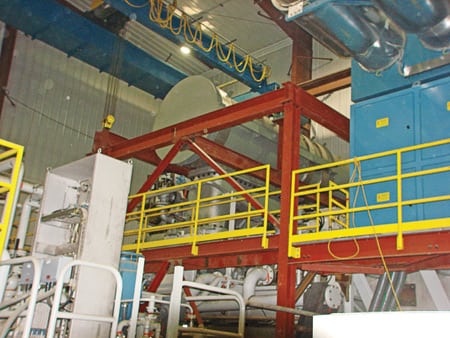
3. Tightly coupled turbines. A GE extraction condensing steam turbine (left) and ABB generator (right) will supply 18 MW of power to the ARPA grid. Extraction steam leaves in a pipe beneath the steam turbine and makes its way to the old turbine building to supply steam to the existing Unit 6 steam turbine. Source: POWER
The unique joining of the old Unit 6 steam turbine and the new Unit 8 steam turbine into an integrated system is one of this project’s innovations. Superheated steam from the new boiler island arrives at the governor valves of the new steam turbine at 1,515 psia and 985F (Figure 4). However, up to 235,000 lb/hr of extraction steam leaves Unit 8 after the first turbine stage and is directed over to Unit 6’s condensing steam turbine. Steam enters Unit 6 at about 850F and 860 psia and can produce 25 MW at full load. The net power delivered to the grid is 38.5 MW.
4. Steam road map. This diagram illustrates how the two steam turbines are interconnected. The top steam flow path is used during start-up of Unit 6 or when Unit 8 is off-line. Extraction steam is used to power Unit 6 during normal operation. Source: LL&P
The operating modes for this twin-turbine arrangement are numerous, and even Rigel admitted that the technicians will need some time to familiarize themselves with the personality of the system and its operating idiosyncrasies under all the possible operating combinations.
Typically, start-up will begin with the top bypass steam line used to warm the long steam line to both turbines. The plant operators’ experience tells them that the Unit 6 turbine, freshly overhauled prior to entering long-term storage in 2003, requires about an hour to warm the steam chest but can roll after about 30 minutes using the bypass steam. When Unit 8 in on-line, extraction steam powers Unit 6 and the bypass line is secured. Both turbines are synchronized to different grid supply points for improved system reliability.
Other operating options are possible. For example, the bypass line, through a pressure control valve and desuperheater, can also direct steam to operate Unit 6’s turbine at full load when Unit 8’s turbine is secured or is unexpectedly tripped. If Unit 6 trips, then the turbine controls are designed to secure the extraction port while reducing main steam flow and staying connected to the grid.
Rigel noted that they are looking forward to exploring the many operating permutations and their limitations in the future. During start-up, Unit 6 will be the preferred operating turbine, and then Unit 8 will be added to the mix.
An Emerson Ovation system was selected for the plant’s digital controls, which interfaced easily with the Cimplicity Control governor system on Unit 8. However, Unit 6 was another story. It was originally outfitted with a pneumatic control system with a single piston main steam stop valve. As part of the turbine upgrade, E-Tech Industrial Services added additional structure steel to lengthen the throttle valve lever arm to accommodate a new Woodward 505 governor and a modern electro-hydraulic actuator so it can communicate directly with the Ovation DCS (Figure 5).
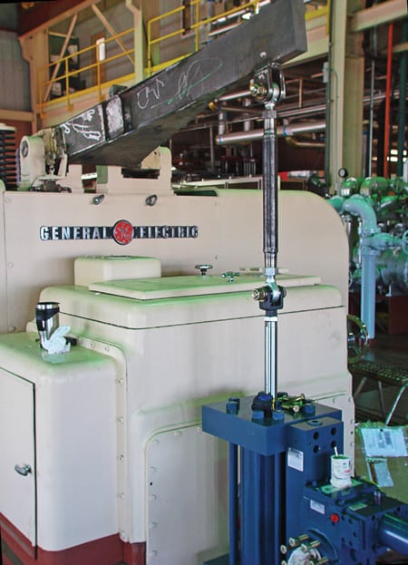
5. Get a grip. A steel extension was fabricated for the Unit 6 governor valve linkage to accommodate a modern electro-hydraulic control system. Source: POWER
Also in the control room, operators monitor and control LL&P’s entire transmission and distribution system, including a Caterpillar diesel set and the five wind turbines.
Cooling water for Unit 6 is once-through supplied by the 17 wells owned by LL&P. The warm-water discharge is sent directly into the agricultural supply canal, so there is no net water loss from the plant. “Water will be somewhat warmer than normal, but not by much, and we have been told that the farmers like the warmer water in the early spring,” said Rigel.
Unit 8 is outfitted with an SPX air-cooled condenser, thereby limiting increased water use by the new plant to less than 20 gpm.
Steam side
The heart of the boiler island is the Babcock & Wilcox (B&W) circulating fluidized-bed (CFB) steam generator designed to burn Wyoming Powder River Basin coal (Figure 6). Coal and a sorbent to capture the sulfur in the fuel—in this case, crushed limestone—is injected through the lower furnace walls of the CFB (Figure 7).
6. Latest and greatest. Babcock & Wilcox supplied the circulating fluidized combustor boiler island, including gashouse and stack. Source: POWER
7. Inside story. This diagram depicts the lifecycle of coal inside a circulating fluidized-bed combustor. U-beams recycle heavier solids back to the furnace bed. Smaller solids are removed by the multi-cyclone dust collector and are also recycled to the bed. The remainder is captured by the baghouse. Source: Babcock & Wilcox
Approximately 50% to 70% of the combustion air enters the furnace through air distributor plates in the bottom of the CFB’s bed. The remainder is injected as overfire air, not unlike the design of a conventional pulverized-coal boiler. However, the similarities end there.
Bed particles are carried upward from the lower furnace with the flue gas, with gas velocity of about 16 to 17 fps at full load, and impact four rows of U-beams in the high-temperature exit of the furnace. According to B&W, average size of bed particles in the lower furnace is 300 to 400 microns, but particles reaching the U-beams are around 100 to 200 microns. The heavier particles remain in the bed area until combustion has reduced their size and the flue gas can carry them out of the furnace and into the U-beam section. The now small and lightweight paricles can only leave the furnace when their momentum is low and they can follow the gas flow around the U-beams. Coarser particles are removed via fluidized-bed coolers (where they are cooled along the way from about 1,550F down to about 400F) connected to the lower furnace.
The U-beams collect on the order of 97% of the solid particles that reach the furnace exit and return them to the furnace, thereby giving the particles more time to complete combustion. Most of the remaining particles that pass through the U-beams are collected in the multi-cyclone dust collectors (MDCs) located in the backpass and are recycled once again to the furnace. This means that about 99.7% of the particles that leave the furnace return to the furnace in short order to complete combustion.
Heat absorption in the furnace water walls maintains the bed temperature at an even 1,500F to 1,600F. The boiler controls manage the amount and distribution of solids inventory and thereby the bed temperature. Controlling bed temperature and the steam generation rate also tightly controls the vertical temperature distribution in the furnace required for proper SO2 removal. Also, by keeping the bed temperature below 1,600F, thermal NOx formation is minimized. The boiler control chores are ablely handled by an Allen-Bradley programmable controller.
Furnace gases exiting the U-beams transfer heat to the steam in the convection pass and then pass over a tubular air heater, filtered by a baghouse designed to remove 99.9% of the particulates, and then are exhausted through a 227-foot stack. Ash removed from the bed is pneumatically conveyed to the ash silo, where it is stored until trucked to the local landfill.
Air permits were reasonably straightforward, at least when compared with much larger central station coal plants. The region around the plant is an attainment area for all pollutants, and the magnitude of the incremental emissions from Unit 8 did not trigger any prevention of significant deterioration (PSD) limits. The only concern was an increase in NOx emissions, but Unit 8 emissions were offset by permanently shutting down the old Unit 6 dual-fuel steam generator.
Balance of plant
An 11,000-foot siding was added to accommodate the 100-car-plus BNSF trains that will arrive every two to three weeks to deliver about 12,000 tons of coal from Jacob’s Ranch, Wyoming. Operators unload one car at a time inside a sealed building held under negative pressure to control fugitive dust emissions. Entering coal cars pause under an inspection station equiped with cameras to detect any hot spots prior to unloading.
Coal is unloaded onto a conveyor located under the tracks (Figure 8) and then conveyed to one of two 60-foot-tall storage domes, each capable of holding up to 6,000 tons of coal. One unique feature of these conveyors is their “clamsheet” design—needed to securely hold coal on the conveyor during a steep climb to the top of the storage domes. Several monitoring devices are mounted inside each dome to monitor for carbon monoxide and coal temperature. Inspection ports on the domes allow the coal to be checked periodically with an infrared camera to detect “hot spots.”
8. No dust allowed. Each rail car that arrives at the plant is first inspected by infrared cameras (top, center) and then unloaded in an enclosed building kept at negative pressure by the dust collection system (center, right). ARPA promised local residents that no dust would leave the plant site. Source: POWER
The coal is drawn out of either dome through another conveyor system to a crusher. Note that the conveyors sit higher on the ground than other systems because groundwater in this area is only 7 feet below the surface during certain times of the year. The crushed coal is conveyed through an enclosed conveyor system to the boiler fuel storage silos, where it is metered into the CFB as required. Sized limestone is fed pneumatically from the limestone storage silo into the lower furnace.
Because the project is located just a block from Lamar’s Main Street, which no one wanted to see coated with a thin layer of coal dust, a rigid dust control design was necessary. Infrared detectors are installed from the rail unloading building to the boiler coal bunkers and each of the five dust collection points the coal passes on its way to the CFB (Figure 9). All the coal transfer points are enclosed and protected by a dust collection system provided by Transcontinental Engineered Products Ltd. (Figure 10).
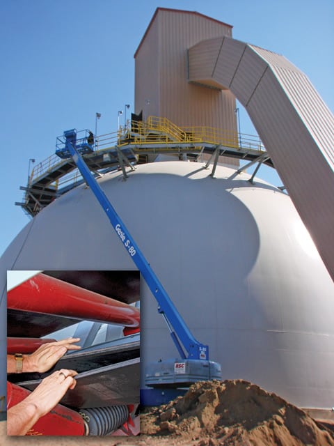
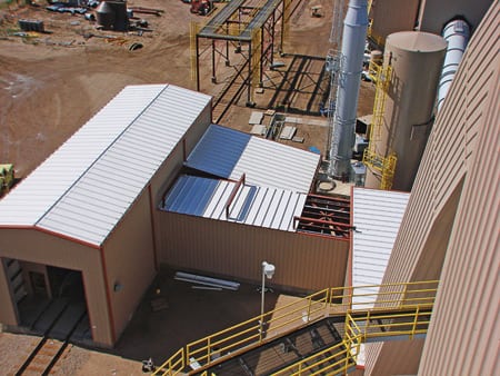
9. Mr. Coal’s wild ride. Coal received from unloading railcars is conveyed to one of the two storage domes. The steep angle of ascent requires a special conveyor design that squeezes the coal between two belts (see inset). Coal is reclaimed at the center of each dome. Source: POWER
10. Keep it clean. Fuel reclaimed from each storage dome moves through a system of conveyors and transfer towers to the boiler’s three storage silos. Each conveyor is completely enclosed, and each transfer point has a dust collection system. Note the two dust collection towers in the center of the photo, one at the transfer tower, and one just to the left of the CFB structure and storage silos. Source: POWER
Also, because the plant sits in an urban setting, much additional effort was made to keep the plant quiet. In fact, the design criterion for the plant is 85 dB at the property line. Designers enclosed the auxiliary motors, pumps, and other auxiliary equipment to comply with the noise ordinance.
Makeup water for the CFB is prepared by a U.S. Water Filtration System reverse osmosis (RO) system using well or city water as the feed source. A 500,000-gallon diesel oil storage tank was cleaned and coated to hold the RO water for initial boiler cleaning. It will also do double duty afterward as the plant’s fire water storage tank.
Challenges overcome
Just because this project was small doesn’t mean it was easy. I would argue that the complexity of the integrated steam turbines makes the design and operation of this plant more complicated than for a standard steam plant.
In fact, the project management team (see table), led by Rich Rigel, ARPA Acting General Manager Alice Jewel, and Staff Electric Engineer Houssin Hourieh, are doing double duty with their day jobs on this project. LL&P is now bringing on more staff, increasing the plant’s workforce from 12 to 14 employees to an estimated 28 employees needed for commercial operation. I’ve seen some lean organizations running projects in the past, but this one’s the leanest I’ve seen in some time.
Major project contributors. Source: LL&P
ARPA originally filed for a construction permit for the repowering project in December 2004 and received the permit in early February 2006. The original project schedule began with the groundbreaking in July 2006. By late 2006 the boiler erection contractor was mobilized. Start-up was scheduled for a very aggressive 22 months after breaking ground and in time for this summer’s peak season. Unfortunately, that goal was not met, mostly for reasons beyond ARPA’s control.
ARPA elected to manage the overall project itself and hired Samuel Engineering to assist. ForeRunner Corp. was retained as the owner’s engineer and detailed designer of Unit 8. ARPA also purchased the major equipment and hired the contractors to install the equipment. The upside of this approach is that you can save the significant markup that comes along with using an EPC contractor. The downside is that you assume the completion risk and bear all the delay costs, even if they are beyond your control.
Generally speaking, the team executed the project by the numbers; however, steep commodity price increases for steel, copper, and concrete during construction pushed up the project’s cost. Also, the location (a three-hour drive east of Colorado Springs) made finding qualified construction labor difficult. Utilities in nearby Pueblo and Holcomb, Kansas, have higher pay scales, which makes it difficult to recruit talented technicians, especially linemen and electricians.
Finally, the specialty reclaimers inside the domed storage enclosures were missing in action when the French company given the supply contract went bankrupt. A U.S. firm purchased the rights to manufacture the reclaimers—but the project still experienced a significant delay. Additional expenses were incurred when temporary enclosed spaces and reclaimers were added to one coal dome so that coal can be unloaded and the boiler supplied with coal. The dome will refitted when the permanent reclaimers arrive.
For figuring out a unique way to minimize generation costs and repurpose existing equipment while maximizing operating flexibility, the Lamar Repowering Project wins this year’s Marmaduke Award.