K-Power Upgrades Combined- Cycle Automatic Generation Controls
Tightly managed grids require combined-cycle plants equipped with power block controls that can quickly respond to automatic generation control signals with minimal error. K-Power’s successful controls upgrade demonstrates that that goal—and more—is achievable.
K-Power Combined Cycle Plant, located in KwangYang National Industrial Complex, is South Korea’s first private merchant power plant (Figure 1). The plant, which entered commercial operation in May 2006, is configured with two power blocks, each one consisting of a 2 x 1 combined-cycle plant. Each 525-MW net power block relies on two General Electric (GE) 7FA combustion turbines (CTs) equipped with dry low-NOx combustion systems, one Nooter three-pressure heat-recovery steam generator per combustion turbine, and a single Hitachi steam turbine.
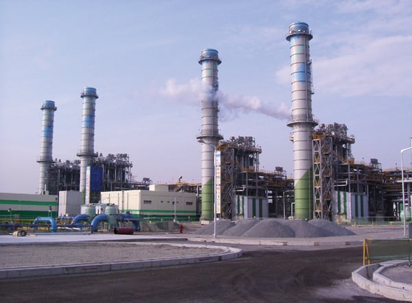 |
| 1. First independent power producer in South Korea. K-Power, a 1,050-MW combined-cycle power plant, was the first merchant power generation facility constructed in South Korea. The plant consists of two power blocks, each based on a 2 x 1 configuration. The plant entered commercial service in May 2006. Courtesy: K-Power |
K-Power (also the name of the plant owner) is a 65:35 joint venture between SK Corp. (a leading Korean energy company) and UK-based BP. The plant is fired with liquefied natural gas imported from the Tangguh field in Indonesia.
K-Power sells electricity to KEPCO, with the Korea Power Exchange (KPX) handling the transactions. To do so, the plant is configured with automatic generation controls (AGCs) that dispatch the plant by power block. K-Power provides KPX with a 24-hour maximum gross generation capacity one day ahead and, in turn, receives a 24-hour dispatch schedule from KPX. The plant receives two dispatch signals (one for each power block) that are frequently updated. The existing plant controls made dispatching to a continuously changing plan very difficult and inefficient. This less-than-optimal process pressed K-Power to consider a controls update.
K-Power’s primary requirement was for an advanced process control (APC) solution that would improve the efficiency of the AGC by minimizing variation from the KPX-provided setpoints. Another goal was to thermodynamically optimize the operation of each power block, within operational constraints, to provide electricity efficiently. Together, these upgrades would ensure that electricity was produced under the prescribed operating conditions as efficiently as possible.
After considering a number of options, K-Power asked GE to supply its “MVC” solution, a model predictive multivariable controller. MVC uses predictive control models derived from plant dynamics and plant simulation results. Nonlinear mathematical models are used to calculate the optimal controlled variables and issue the corresponding manipulated variable setpoints on each execution cycle. Automatic bias maintains the predictive integrity of control models under varying plant conditions.
How AGC Works
When the plant is operating, the AGC receives two dispatch signals, one per power block, every 10 to 15 minutes. The signals received are the new setpoints for total gross power required per power block. For planning purposes, K-Power sends to KPX a day-ahead, 24-hour maximum gross generation capacity based on current equipment performance and anticipated ambient conditions. The dispatch signals sent from KPX to the plant will be within the maximum gross generation estimated, given the expected operating constraints.
The original CT control strategy was quite ordinary. CTs were loaded using the “preselect” mode once the power block reached an acceptable stable condition after the generators were synchronized with the grid. Once the CTs reach their preselect conditions, the load control setpoint can be raised, lowered, or set to baseload, and the CTs will respond in tandem. If controls are set to baseload, the CTs ramp up to that condition based on the control settings within the Mark VI (GE’s CT control package). The design CT ramp rate is 5 MW per minute (manual) and 3 MW per minute (automatic), according to the Mark VI system specifications.
When the load on each CT is increased such that the measured exhaust temperature reaches the prescribed baseload temperature control limit, the CT output is then said to be operating at baseload conditions. Once at baseload, the CTs operate on the baseload inlet guide vane/temperature control curve. Under certain ambient and operating conditions, the CT may be limited by this control curve even though expected baseload output is reached—a not-unusual scenario under high ambient temperatures. The power demand signal is directed to the Mark VI CT digital controls from the plant distributed control system (DCS) to produce the required electricity.
The updated CT control strategy is a remarkable improvement. The MVC controller sends supervisory megawatt (MW) setpoints to the DCS for the operating CTs. In turn, the DCS sends a setpoint signal directly to the Mark VI CT controller, just as before. Modified control logic in the DCS allows the operator to select “computer Mode” for the individual CTs, which enables MVC control. computer mode is an added operating mode now programmed in the DCS in addition to the “baseload” and “preselect” modes discussed above.
MVC takes control of the CT MW setpoint when the operator selects computer mode and the Mark VI remote control is enabled. The MVC is only used when the CTs are operating and is secured before CT shutdown.
During start-up, the MVC has high and low MW and maximum MW ramp rate limits defined for individual CTs. A feedback signal from the Mark VI indicates when baseload conditions have been reached. That signal is used in the MVC controller to set the high limit of the controller. The MVC high limit is set as the current output of the CT plus three times the maximum ramp rate (that is, 9 MW) until the feedback signal indicates that baseload (or maximum output based on operating conditions) has been reached.
When baseload has been reached, the high limit is set at current output plus 0.5 MW. This 0.5-MW margin allows for the normal oscillation of the CT output and for maintaining the turbine at stable baseload condition. In this way, the MVC optimally controls the online CT MW setpoints to meet the K-Power dispatch commitment. Table 1 summarizes many of the other plant design constraints in the MVC that will limit the power block ramp rates.
 |
| Table 1. Plant ramp rate constraints. The speed at which a power block’s output can be increased or decreased is limited by equipment design. For example, a minimum value of steam flow to the block 1 steam turbine must be available before the desired combustion turbine MW ramp rate can be achieved. Source: GE Power |
MVC System Architecture
Figure 2 depicts the communication interface between the K-Power DCS and the GE Bently Nevada EfficiencyMap/CLOC (closed-loop optimal control) computers. EfficiencyMap is plant optimization and performance monitoring software designed to measure, predict, and track plant performance. CLOC is a supervisory control and optimization system for complex, dynamic processes.
 |
| 2. MVC data communications at K-Power. Source: GE Power |
The MVC software and plant historian are installed on one computer; EfficiencyMap is installed on a second computer. The plant historian, hosted on the CLOC computer, communicates with the plant’s Honeywell DCS OPC server via the historian-OPC interface. The CLOC system does not communicate directly with the turbine controllers. All communications pass through the DCS OPC server, and the necessary information (such as operating parameters and setpoints) is communicated to and from the CT controllers to the DCS via OPC protocol. To facilitate receiving incoming data, the Honeywell DCS has additional logic programmed to ensure that the incoming data is permitted and will not adversely affect the control system.
Scheduling and Planning
The system also includes an off-line GateCycle “what-if” tool. This tool, in the form of an Excel spreadsheet, is used by plant personnel for what-if parametric studies. It implements full-plant equipment models and can be “tuned” to the latest plant conditions.
The tool allows the user to accurately forecast maximum power that can be generated from the two power blocks under a variety of operating conditions. To forecast the maximum power generation possible, the user must input the following parameters:
- CT inlet pressure drop
- CT exhaust pressure drop
- Ambient temperature
- Ambient pressure
- Relative humidity
- Cooling water inlet temperature
- Current level of CT degradation
The CT inlet pressure drop, exhaust pressure drop, and current CT degradation can be obtained from the online EfficiencyMap system. The user can also estimate the maximum power generated by each block under “new and clean” conditions.
K-Power generates the forecast for the next 24 hours using these tools and then sends the forecast to KPX based on the lowest, highest, and average expected ambient temperatures. After receiving the load profile from K-Power, KPX sends the load profile for the next day back to K-Power by 18:00 hours. The load profile is then converted to a continuous AGC signal, which MVC uses to control plant output by manipulating the power setpoint of the individual CTs.
Commissioning New Controls
A long-term commissioning plan was established at the project kickoff. A complete team charter was also developed to define the roles and responsibilities of the GE engineers and K-Power staff. The MVC commissioning plan had five stages:
- Instrument input/output checkout
- DCS level configuration checkout
- Plant step testing and APC controller tuning
- Model building and implementation
- Site acceptance test
The start-up team included GE commissioning engineers working on DCS-level configuration checks to ensure that the plant was well protected during all anticipated operating scenarios and that switching between different control modes (such as APC control, automatic, and manual functions) was bumpless. Additional configuration changes were made to ensure that the regulatory controllers defaulted to safe mode in the event of failure of the supervisory computer.
Before plant step tests, all DCS level control loops were checked to make certain all the basic regulatory controllers were properly tuned. These were not just APC-related loops but also other loops that improved unit stability and ensured smooth plant operation. The GE engineer developed the DCS logic changes, and the K-Power DCS engineer approved the logic changes and implemented the logic changes on site during scheduled outages. GE and plant engineers tested the logic changes thoroughly before the power blocks were returned to operation.
Full involvement of plant staff, especially the operations staff, is critical for the success of any APC implementation. During the step testing phase of MVC commissioning, for example, plant operators were fully involved. Continuous and frequent interaction between the GE engineering team and operating personnel allowed the GE engineering team to learn about the intricacies of plant operations. In turn, the plant operators learned more about multivariable control.
Operator Training
The plant operators are the primary users of the APC system, and proper operator training is a critical component of a successful APC project. Formal operator training consists of a systematic and comprehensive training program, which is normally held after commissioning and prior to the site acceptance test. At K-Power, operators were trained on APC fundamentals as well as hands-on usage of the APC system during project implementation and post-commissioning.
The APC training material covered basic process control concepts, DCS-based advanced control concepts, multivariable control concepts, and the MVC system. Human machine interface and K-Power-specific control strategies and operational procedures were also discussed.
During the hands-on APC system training, the GE engineer explained the control strategies specific to this project and how the multivariable controllers move manipulated variables to satisfy setpoint variables and constraint variables under different scenarios. Operators were trained how to activate and deactivate MVC, how to perform minor troubleshooting, and how to handle system start-up and shutdown. An operator’s manual was provided at the end of the training. An ongoing supporting services agreement ensures that the benefits derived from the MVC, EfficiencyMap, and what-if tools continue into the future.
Post-APC Performance
The MVC was successfully commissioned at K-Power in October 2007. Thanks to a user-friendly operating interface, a single-window philosophy of operation, and proper training, operators have readily accepted the APC system. This system has achieved measureable benefits for K-Power, such as improved closed-loop AGC control, stable plant operation, and increased operator understanding of process interactions.
A study was conducted in February 2010 to assess the long-term benefits of the MVC. In sum, the APC has provided increased stability in plant operations, and the variation of important plant operating variables has been reduced by a minimum of 30%. These results are seen in the test data, showing the standard deviation calculated between the MVC On and Off conditions, for each power block (Table 2).
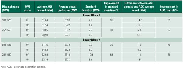 |
| Table 2. Power block test results. An assessment of the MVC performance was conducted about two years after the system was commissioned. The performance improvement of the plant on AGC control was remarkable. Source: GE Power |
The MVC has also reduced the variations in overall power generation. With MVC control, overall power generation is controlled closer to plant targets than without MVC control. A minimum 27% improvement was observed. Figures 3 and 4 illustrate the improvement in AGC control between MVC Off and On for each power block. The test data clearly shows that when MVC is On, the average actual MW is closer to the average AGC MW.
 |
| 3. Power block 1 MVC performance test results. Source: GE Power |
 |
| 4. Power block 2 MVC performance test results. Source: GE Power |
A less-quantifiable, but nevertheless important, benefit of the APC is improved operator perception of process interactions and understanding of optimum operating conditions. Process interactions are more clearly visible to operators as the controller simultaneously manipulates variables to maintain a controlled variable at its target value. A plant staff that understands how the MVC works is much more valuable than one that knows only which to buttons to push.
— Sang-joon Park is the GE Energy O&M operation manager for K-Power. Gaurav Gupta ([email protected]) is service manager, LeeMary Ma ([email protected]) is lead technical specialist, and Uttam Narasimhan ([email protected]) is lead application engineer for the Performance & Optimization group in GE Measurement & Control Solutions.