Gas turbines require clean gas to operate efficiently. Particulate contamination fouls fuel nozzles, causes increases in flue stack emissions, and occasionally causes unplanned plant outages. Now a new real-time natural gas cleanliness monitoring and web-based alarm system is providing valuable protection for natural gas–fired power plants. The adaptation of laser light–scattering technology for the purpose of contaminant measurement in high-pressure gaseous pipelines provides a method of monitoring liquid and solid contamination levels.
In order to protect gas turbine (GT) power generation facilities against the threat of particulate contaminant, plant operators install fuel gas conditioning systems. Additionally, plant personnel at natural gas–fired power plants rely heavily on gas sales contracts to ensure that purchased natural gas is tariff quality.
Even with these safeguards in place, contaminant-related performance problems can take GTs off the grid. Fuel gas conditioning systems typically fail due to poor design or equipment malfunction. And gas sales contracts do not provide recourse because they cover gas quality but fail to quantitatively cover gas cleanliness. A common gas contract clause will state that the gas particulate contamination must be at a level at which no downstream equipment or process will be harmed. Once the GT is down and the damage has occurred, however, there is little an operator can do to prove the fuel used was off spec.
Fortunately, a real-time natural gas cleanliness monitoring and web-based alarm system that offers valuable protection for natural gas–fired power plants is now available. The ability to monitor pipeline cleanliness helps GT operators correct contaminant issues before equipment damage can occur.
Contamination Sources
Processed, clean, tariff-quality natural gas should be ready for the combustor nozzle. All too commonly, however, it is not. It is still typical for liquid and solid contaminants to reach and damage gas turbines. Experience suggests that pipeline contaminants invade point-of-use facilities for a number of reasons.
Hydrocarbon Dew Point. The hydrocarbon dew point of a gas stream is the point at which the temperature and pressure of the system are right for certain components of the natural gas to condense out of the gas in the form of liquid droplets. Standard fuel gas conditioning design suggests that the gas stream be superheated to at least 50F over the hydrocarbon dew point and/or moisture dew point, whichever is higher. The superheat temperature is usually set substantially higher than the operating temperature to help cover the effects of atmospheric temperature drops and pipeline fitting pressure losses that result in temperature losses.
Atmospheric temperature drops and pipeline fitting pressure losses can produce natural gas liquid condensate in the last few feet of the fuel gas piping between the fuel gas conditioning skid and the combustor nozzles. Cool morning atmospheric temperatures can reduce the skin temperature of the fuel gas conditioning skid equipment to the point where natural gas liquids can nucleate out of solution onto the walls of fuel gas piping and sometimes even the walls of the gas coalescer filters that are in place to remove such liquids.
Pipe fitting temperature losses are usually realized via a Joule-Thomson effect caused by a pressure reduction or control valve. The Joule-Thomson effect is an isoenthalpic expansion of natural gas that results in a temperature loss. If the temperature loss drops the gas temperature to the dew point temperature or lower, liquids will condense out of the gas stream, creating a new contaminant that GT operators have to deal with.
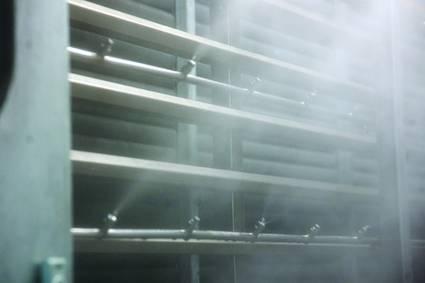
Compressor Lube Oil Carryover. Frequently, fuel gas booster compressors are included on-site to keep fuel gas streams at the specified operating pressure. Compressors are a consistent contributor of lube oil contamination to fuel gas pipelines. Reciprocating compressor lube oil losses have been measured up to 7 gallons per day per compressor. The lube oil aerosol carryover is normally removed with a filtration vessel called a filter coalescer. Failures normally occur when the filter coalescer is overwhelmed with more liquid contaminant than it can handle.
Rotary or screw type compressors are also sometimes used to give a final boost to fuel gas pressure. Rotary compressors utilize lube oil to cool the compression screw and to seal rotating components during the compression process. In order to perform rotary compression, lube oil is discharged with the compressed gas. A large coalescer, which is called a gas oil separator, is used to separate lube oil from the gas stream.
In addition, rotary compressor gas oil separation is extremely difficult, as the lube oil reaches temperatures as high as 220F, which greatly lowers its surface tension and viscosity. The other component that makes separation difficult is the volume of liquid present that must be separated. Rotary compressors have lube oil circulation rates between 10 and 150 gallons per minute. These volumes provide a massive opportunity for lube oil carryover. In fact, rotary compressor gas oil separators are notorious for allowing extreme amounts of lube oil carryover.
Poorly Designed Filtration Systems. Filter coalescers are normally designed with two stages. The first stage collects the liquid film or free liquids that travel on the pipe wall, usually by gravimetric means. The second stage utilizes a number of coalescer elements designed to remove solid and aerosol particles from the gas stream.
A target specification for liquid removal for a GT fuel gas filter coalescer is 10 ppb by weight. Well-designed coalescers can easily meet this requirement. Poorly designed coalescers will struggle to produce an effluent this clean. Filter coalescer performance issues usually originate from problems with the vessel or housing design.
- Common filter coalescer vessel design mistakes include the following:
- Skimping on the first-stage free liquid knockout area.
- Placing the coalescer elements too close to one another.
- Locating the outlet nozzle in an area that causes the gas to channel and not fully and equally utilize all of the available coalescing media.
The coalescer elements also play an important role in removal performance. GT operators need to heed the following warning: Not all coalescer elements are the same. Most elements can meet the target removal requirement. Elements differ, however, in their liquid handling capacity. Some coalescer elements are available that will handle 5,000 ppm by weight inlet liquid contaminant, while others will handle as low as 5 ppm. Fuel gas conditioning filter failures are a common source of combustor nozzle contamination.
All of these issues routinely result in new contaminant challenges for point-of-use fuel gas conditioning systems. If the contaminant loading is more than the system can handle, or if the dew point requires more heat duty than the heater can deliver, contaminants will make it to the combustor nozzles.
Pipeline Contaminant Behavior
Problematic fuel gas contaminants normally break down into the following categories:
- Pipeline corrosion-produced solid particles
- Hydrocarbon condensate
- Lube oil
- Pipeline injection chemicals
- Water droplets
Solid particles are typically easy to remove with quality filter elements that are properly designed to handle the solid’s physical characteristics and content. In contrast, the presence of liquid droplets or mist contamination is normally more troublesome, as liquids can condense out of the gas and are subject to shear.
 |
| Go with the flow. This table shows natural gas flow data for two gas turbine power plants. The calculated Reynolds number is well within the turbulent flow regime. Source: PECOFacet/Scientific Process Solutions Inc. |
Fluid streams under turbulent flow produce a mass of flow eddies of various sizes. Each flow eddy will contain a definite amount of mechanical energy. Turbulent flow also produces deviating velocities in a pipeline. The combined effect of flow eddies and turbulent flow deviating velocities greatly enhances the shear forces in a turbulent environment. Turbulent regime shear forces are commonly referred to as Reynolds stresses. The table contains measured natural gas flow data for two GT power plants.
The calculated Reynolds numbers (interpreted physically as the ratio of a fluid’s inertial forces to its viscous force) for Plant 1 and Plant 2 in the table are both around 3 x 10⁶—well within the turbulent flow regime. A Reynolds number above 2,000 is considered to represent turbulent flow. The frictional effect of the pipeline wall on gas velocity must be taken into account when studying pipeline flow. The gas flow rate at the pipeline wall will be almost zero in the laminar flow region. Gas velocity will increase as you move away from the pipe wall toward the center of the pipe, where the highest gas velocity is found and the gas is in the turbulent flow regime. Figure 1 provides a computational fluid dynamics illustration of a pipeline gas flow profile based on the Plant 1 data.
 |
| 1. A pipeline profile. This computational fluid dynamics model illustrates a natural gas pipeline gas velocity profile based on Plant 1 data. The profile shows a velocity cross section of an 8-inch pipe with methane at 55 ft/s and 494 psig. Source: PECOFacet/Scientific Process Solutions Inc. |
The forces or Reynolds stresses found in a turbulent fluid can shear liquid particles present in the fluid stream. Droplet shear will occur if the Reynolds stresses exceed the droplet’s internal surface forces or surface tension. Droplet surface tension is defined as cohesive intermolecular forces located at or near a liquid droplet’s surface. These forces work to hold the droplet together in a spherical shape. The surface tension of water is 73 dynes/centimeter (cm), whereas hydrocarbon liquids are in the 20 dynes/cm range. Under turbulent flow, a hydrocarbon droplet will shear much easier than a water droplet. This phenomenon causes hydrocarbon droplets, and other liquids with relatively low surface tension, to be more difficult to remove.
A simple way to predict when shearing will occur is to look at a droplet’s Weber number, the ratio of a fluid’s inertial force to a droplet’s surface tension. A Weber number of 13 for a gas system is considered the critical number at which shear will start to occur.
The smallest stable droplet sizes for Plant 1 and Plant 2, as shown in the table, were calculated based on using the Weber equation with a Weber number of 13 at the average pipeline velocities. A smallest stable droplet size of 55 microns was calculated for Plant 1’s fuel gas process conditions. Plant 2’s data produced a smallest stable droplet size of 181 microns. In order to obtain a visual indication of these particle sizes, the largest water droplet that can fall through the air is 8,000 microns, or about 0.32 inch. The maximum size of hydrocarbon droplets in the fuel gas systems of Plant 1 and Plant 2 is in the range of dust particles.
Large droplets cannot exist in a turbulent flow pipeline except in the laminar region next to the pipe wall. If a pipeline’s aerosol content is large enough, aerosols will coalesce due to droplet collisions and pipeline wall interaction. Once these particles are in the laminar flow layer, they can build up and form a traveling film of liquid. Unfortunately, a traveling film of liquid actually provides the highest potential for causing GT performance issues. It is generally accepted that GT fuel gas should have no more than 10 ppb liquid contaminant. Experience suggests that liquid films do not develop in a system where the liquid content is kept at or below this level.
Method for Gas Pipeline Contaminant Monitoring
Natural gas–fired power plants utilize gas chromatographs to monitor gas quality and the energy level of fuel gas. A gas chromatograph will monitor the percentage of each of the gaseous components and can even be set up to check for the presence of gaseous contaminants like H2S, CO2, and nitrogen. However, a chromatograph can not be used to accurately monitor the presence of pipeline liquid and solid contaminants. Gas chromatographs utilize filtration systems to protect their gas separation columns by removing such contaminants prior to analysis.
A technology has been developed to monitor solid and liquid contaminant levels in high-pressure gas pipelines. Contaminant monitoring in high-pressure volatile gas pipelines produces a special set of design challenges. These two design challenges have eliminated many promising technologies from the application of particle contaminant monitoring and measurement in gas systems:
- The gas must be sampled and analyzed at pipeline pressure and temperature. Changes in pipeline pressure and temperature will condense or vaporize some gas components and may change the size and number of other contaminants.
- Contaminants coat sensor surfaces over time, resulting in output signal changes.
When selecting a technology to perform contaminant measurement, the fluid mechanics of how contaminants behave in a pipeline must be considered. Understanding the combined effects of turbulent and laminar barrier flow on typical pipeline contaminants is key. For example, the data in the table for Plants 1 and 2 are very typical for gas turbine fuel. The data from these plants tell us that most fuel gas lines are fully turbulent. We also have calculated that droplets larger than typical household dust are going to be sheared and atomized into smaller aerosol droplets. If the liquid contaminant content is high enough, a liquid film will build up in the laminar flow boundary layer. The laminar to turbulent transition layer is going to place the gas liquid interface under constant shear conditions. Gas liquid interface sinusoidual wave fragmentation will occur.
Therefore, we concluded that if liquid is present, it will be in aerosol form at low liquid concentrations and a combination of aerosol and film flow at higher liquid concentrations. In either case, aerosols will be present.
A contaminant measurement and monitoring technology must be used that can detect and measure aerosols as well as solid particles, if they are present. The technology must also handle contaminant coating and perform its analysis at pipeline pressure and temperature. As particle size measurement was determined to be the most important parameter to monitor, laser-produced light-scattering technology was selected for the application. Laser particle counters have gained wide acceptance as clean room dust and aerosol monitors (Figure 2).
 |
| 2. Tracking down contaminants. The PlantGard high-pressure gas pipeline contaminant monitor can detect and measure aerosols and solid particles. Data from the monitoring system are normally communicated by serial or analog cable to plant digital control systems. Source: PECOFacet/Scientific Process Solutions Inc. |
The system developed includes a sampling probe that is inserted about one-third of the way past the pipeline wall. The sampling probe will flow a continuous sample of gas up through a sampling line that feeds the laser particle-counting flow cell. After passing through the flow cell, the discharge gas is pumped back into the pipeline with a pneumatic-driven compressor that is an integrated part of the monitoring system.
 |
| 3. On the alert. The PlantGard web dashboard is shown recording changes in the natural gas’s cleanliness. Source: PECOFacet/Scientific Process Solutions Inc. |
Data from the monitoring system are normally communicated to the plant digital control system (Figure 3). A real-time data stream is also web-based for secure viewing from any Internet connection. Particle count trend lines are monitored for each particle size channel or registry. Alarm level thresholds are set for critical registries. Increasing levels of contaminant will always increase the particle count. Experience has proven that film flow will produce a proportionally increasing aerosol content as the film content increases. The particle count data are used to measure the relative amount of contaminant flowing in the line (Figures 4 and 5).
 |
| 4. Clean bill of health. The clean gas flow in the pipeline illustrates normal clean gas fuel conditions. Source: PECOFacet/Scientific Process Solutions Inc. |
 |
| 5. Caught in the act. The wet gas flow in the pipeline illustrates a liquid contaminant upset. Source: PECOFacet/Scientific Process Solutions Inc. |
Particle size distribution data help indicate what’s happening in a pipeline. For example, a coalescer element seal failure will continuously produce particles in the 1- through 8-micron range, whereas a properly working filter coalescer will have an effluent stream containing only low levels of particles less than 1 micron. A coalescer element starting to lose its removal efficiency due to solids loading will produce a gradual increase over time of all particle sizes. Liquid slugs from the upstream pipeline result in an immediate jump in particle counts. Cataloging contaminant events to their resulting particle size distributions has proven to be a powerful diagnostic tool.
New Technology Improves Plant Performance
The innovative use of laser light–scattering technology is an effective method of monitoring liquid and solid contamination levels in high-pressure gaseous pipelines. Turbulent gaseous pipeline aerosol behavior produces a contaminant particle size distribution that can be used to diagnose process problems and filtration equipment performance. The technology’s ability to monitor fuel gas cleanliness levels is providing data that are now being used to successfully confirm the quality of gas supplies and troubleshoot plant performance issues.
—David Burns (davbur@pecofacet.com) is vice president of research and development at PECOFacet/Scientific Process Solutions Inc., a Clarcor Company. Scientific Process Solutions Inc. provides natural gas pipeline contaminant measurement, monitoring, and filtration analysis services for natural gas–fired power plants.