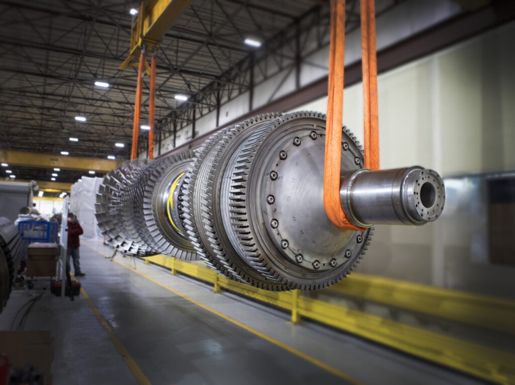
Extending the economic operating life of aging steam plants remains a priority at many utilities, given the challenge of obtaining permits for new generation and the lower cost of life-extension projects. More than half of U.S. coal-fired plants are over 30 years of age, and 10% are more than 50 years old. These veterans still have a lot of fight left in them, given an overhaul or two. But such work can uncover unexpected ailments, as operators at the aging Cromby Generating Station (Figure 1) learned.
|
1. Fifty years and counting. Exelon’s Cromby Station has been in commercial service for more than 50 years. Upgrades to Unit 2’s steam turbine should extend the plant’s life for a couple more decades, at least. Courtesy: Exelon Corp.
|

Exelon’s Cromby Generating Station, located in Phoenixville, Penn., consists of two units: Unit 1 is a coal-fired 144-MW plant; Unit 2 is a 202-MW unit that burns gas or No. 6 fuel oil, depending on market conditions. Unit 1 has accumulated more than 330,000 fired hours since it began commercial service in 1954. Unit 2, commissioned in 1955, remains a favorite dispatch unit in the Exelon fleet and dispels the myth that “it’s the miles and not the age” that determine when a unit should be retired.
Rotor transplant
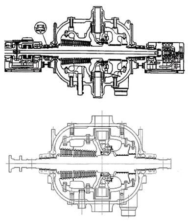
Unit 2, the focus of this case study, is a conventional steam plant with a three-casing, single-driveline steam turbine (one HP, one IP–single-flow LP [IP-SFLP], and one double-flow LP [DFLP]) originally built by Westinghouse (Figure 2). Mitsubishi Power Systems Inc. (MPS) was awarded a contract to retrofit and upgrade the steam turbine to extend its service life. Generating 4% more power with the more-efficient turbine was a welcome side benefit of the project.
|
2. Long driveline. The rotor arrangement of Unit 2 at Cromby Generating Station. Source: MPS
|

Figure 2 also illustrates the unit’s rotor bearing arrangement. In this configuration, bearing No. 4, between the IP-SFLP and the DFLP (bearing No. 5), is shared by the two cylinders. Figure 3 compares cross sections of the old and replacement HP steam turbines.
|
3. Fits like a glove. Mitsubishi Power Systems engineered a new direct replacement HP steam turbine to fit inside the casing of the old steam turbine. Shown are cross sectional drawings of the original (top) and new (bottom) HP steam turbines. Source: MPS
|
The retrofit project replaced the HP rotor and diaphragms but reused the existing outer casing. The original Curtis control stages were replaced with a single, higher-efficiency Rateau stage, and the reaction blades were redesigned with the latest 3-D design tools. The HP turbine’s inner casing, blade, and dummy rings were replaced; the HP rotor bearings were rebabbitted; and thermocouples for bearing metal temperature were installed. Farther down the driveline, one row of LP L-0 blades and three rows of LP L-1 blades were replaced. The addition of orthogonal vibration measurement instrumentation completed the scope of work. Plant engineers showed excellent foresight in adding this new vibration instrumentation—as you’ll appreciate in a moment.
The upgrades were completed without incident, and the unit was started on November 17, 2003, for testing. Loading of the unit and overspeed tests were also performed without any major problems. However, vibration instability, or oil whirl vibration, in the HP bearings at low-load operating conditions was soon observed. In the following days, several field balancing runs were performed to reduce the vibration levels of bearings 3, 4, and 5. On November 20, after sustaining low-load operation for several minutes, a rather sudden synchronous vibration increase was recorded in bearing 2 (and in bearing 1 to a lesser extent) that prompted a trip of the unit.
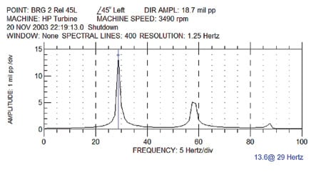
During the coast-down, a sudden subsynchronous vibration spike was recorded at approximately 3,500 rpm with a filtered 0.5X value in excess of 15 mils (with direct readings of almost 20 mils).
Bad vibes
The old HP turbine had had a history of unstable behavior before the retrofit and had experienced sporadic subsynchronous vibration. However, pre-outage detailed vibration data were not available for precise analysis because the unit was not equipped with the instrumentation package found on late-model turbines.
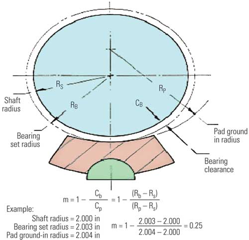
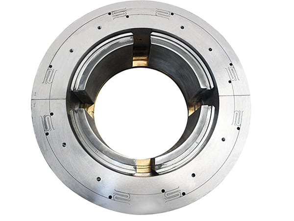
The rotor bearing system stability of the HP turbine with the original “partial center slot type” bearings (Figure 4) had been analyzed before the outage and was found to be satisfactory with the heavier new rotor. The option of making dimensional changes in the center slot to improve the stability margin was dismissed because of the relatively elevated drain temperature of the HP bearings (180F for an oil supply of 104F).
|
4. Recycled bearings. The HP turbine’s lower-half bearings with a partial center slot were analyzed as part of the retrofit turbine design and were found to be adequate for the new, heavier rotor. All bearings were rebabbitted during the project. Courtesy: MPS
|
Vibration data collected on November 19 (before the trip) still showed sporadic subsynchronous vibration, which now appeared during the acceleration ramp-up at approximately 2,840 rpm and disappeared at approximately 3,490 rpm (Figure 5). This sporadic behavior continued during several subsequent operational tests when loading the unit to baseload operation. The only common thread was the unpredictable timing of the vibration.
|
5. Unexpected spike. Subsynchronous vibration during a start-up with the new HP turbine is shown inside the red circle. Source: MPS
|
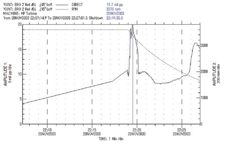
The team determined that the high synchronous vibration recorded on November 20 was caused by a severe rubbing condition between the shaft and the bearings experienced during a normal shutdown, causing the unit to trip on high vibration. The internal rubbing was quickly identified by a large and rapid increase in the synchronous vibration component with large changes in phase angle (Figure 6). At the moment of the trip, the subsynchronous component was negligible, but it suddenly increased during the coast-down that followed the trip (Figure 7). Overall (nonfiltered) vibration during coast-down after the instability was triggered approached 20 mils (Figure 8).
|
6. Rubbed the wrong way. A large synchronous vibration excitation in the HP turbine was induced by a rubbing condition. The polar plot shown is for bearing No. 2. Source: MPS
|

|
7. Stuttering stop. A sudden increase in subsynchronous vibration during coast-down was also caused by rubbing. Source: MPS
|
|
8. Shake, rattle, and roll. Overall vibration reached 19.7 mils peak-to-peak during the coast-down after the trip. Source: MPS
|
Flexible shaft
The original steam turbine design included bearing vibration measurement in only one direction. The upgrade’s scope of work added additional, orthogonal vibration measuring capability on all bearings. This new instrumentation also allowed operators to gather shaft average centerline data, which was extremely helpful in diagnosing the new HP turbine’s vibration problems.
Figure 9 illustrates the average centerline of bearing 2 from cold start-up conditions (bottom of the plot) to the relatively hot shutdown conditions (last point to the right). The plot clearly indicates a shift of the rotor centerline toward the right side of the bearing during operation. Additionally, the rotor’s stationary position was displaced, relative to its pre-starting position, by almost 5 mils after stopping, in both vertical and horizontal directions.
|
9. Tracking shaft movement. Newly installed instrumentation added the ability to track the HP turbine shaft average centerline. This chart shows the shaft movement inside bearing No. 2. Source: MPS
|
The only explanation for this behavior is either actual movement of the shaft center to the right side of the bearing (in the opposite direction of the expected shaft locus) or relative movement of the sensor with respect to the bearing center.
Tracking sensor movement relative to the shaft. Bearing No. 2’s vibration sensors were installed in the pedestal cover at a relatively long distance from the rotor surface. Thermal expansion–caused movement of the pedestal cover relative to the bearing resulted in the misleading indication that the rotor position at rest, before starting, and after shutting down had changed.
Investigators determined that the induced movement of bearing 2’s pedestal cover did result in the erroneous conclusion that the rotor position at rest was different at cold and hot conditions and that this was not part of the root cause of the vibration increase.
Factoring in the steam turbine valve sequence. Steam is admitted to the HP turbine through eight different nozzles located in the periphery of the HP turbine’s first stage. The nozzles are designed to gradually open during start-up to carefully control steam flow into the turbine’s governing stage. Investigators found that the order in which the eight nozzles are sequenced affects the bearing loading as the direction of the reaction force on the rotor changes (Figure 10).
|
10. Order matters. HP turbine bearing No. 2 loading was found to be a function of the generator load and the sequencing order of the eight nozzle valves. Source: MPS
|
Whenever nozzle valve 3 opens (at around 60 to 70 MW), a bearing load increase is observed. Bearing loading is clearly reduced after nozzle valve 4 opens at approximately 50% load (about 100 MW). The governor valve sequence related to 25% and 50% steam admission flow corresponds to the lightest load condition of the rotor, and it unloads bearings 1 and 2. A moment is also introduced that affects loading conditions on bearings 1 or 2, depending on the nozzle valve sequence.
Measuring the uneven movement of bearings 2 and 3 thrust pedestals during thermal expansion. The horizontal thermal expansion of the bearing pedestal between the HP and the IP-SFLP turbines was measured by installing dial gauges at the base of the pedestal base plate. Measurements revealed uneven movement of the pedestal referenced to the shaft centerline.
Measurements of the horizontal movement of the pedestal between HP and IP-SFLP turbines revealed uneven thermal growth displacement. This movement induced angular deviation between the rotor and bearings 2 and 3. This deviation caused movement of the rotor at bearing 2, away from the normal shaft centerline position on the right side of the bearing.
Pedestal movement readings at the generator and governor ends of the driveline were significantly different (Figure 11). The relative end-to-end change in pedestal position was a maximum of +6 mils and a minimum of –5 mils. This displacement caused the observed angular deviation of the bearing with respect to the rotor centerline. The lower chart in Figure 11 shows the loading condition of the unit during measurement of the pedestal’s horizontal movement.
|
11. Measuring movement. The horizontal thermal growth of the pedestal between the HP and IP-SFLP turbines was measured during a typical turbine start-up, at full-load operation, and then at 25% load. Source: MPS
|
Inspired solution
The stability margin of the replacement rotor-bearing system was analyzed throughout the entire range of loading conditions. Particular emphasis was placed at 25% load, where the rotor bearing system has the lowest loading. Bearing metal temperature data were also collected during the turbine tests and revealed additional clues to the root cause of turbine vibration (Figure 12). The metal temperature “mirrors” the changes in calculated bearing pressure changes induced by the governor valve sequencing. This is clearly confirmed by a comparison of the trends in Figures 10 and 12.
|
12. Temperature fluctuations. Bearing metal temperatures were also measured as a function of load. The general shape of the curve is similar to the bearing loading shown in Figure 10. Source: MPS
|
The subsynchronous vibration experienced by this plant for many years before the upgrade project had been sporadic and insignificant enough to have no appreciable impact on total measured vibration. After all, if a variable isn’t measured, trend analysis isn’t possible. This “dormant” unstable condition was theorized to be the cause of the sudden increase in the subsynchronous component due to an unknown and unexpected excitation. In this particular case, investigators determined that the rubbing condition (illustrated in Figure 6) was the excitation source causing the sudden increase in subsynchronous, or oil whip instability, vibration.
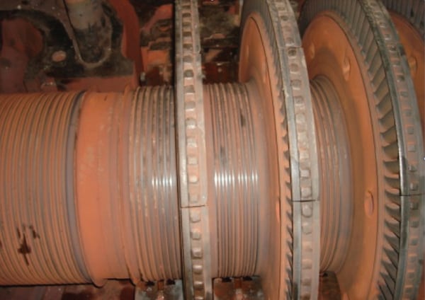
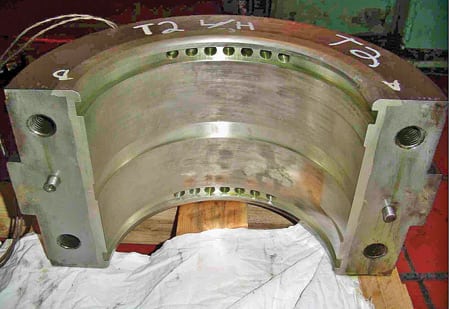
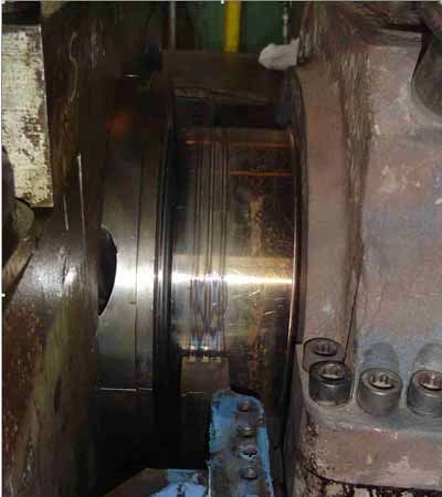
But what caused the original rubbing, especially given that the turbine was initially started and loaded without any evidence of rubbing? Evidence of the rubbing was clearly seen in a photo of the labyrinth seals taken after excessive vibration was observed during the November 20 coast-down (Figure 13).
|
13. There’s the rub. Evidence of rubbing found after the large vibration event. Courtesy: MPS
|
The solution to both observed problems was to increase the stability margin of the rotor-bearing system by modifying the bearing geometry. This one modification increased the stability margin of the HP rotor-bearing system under rubbing conditions and nozzle valve bearing-loading conditions.
The original HP bearings were of the “partial center slot” type with a 0.96-inch slot in the lower half. The HP bearings were modified by increasing the slot width by 0.61 inch—to 1.5 inch—in order to increase the HP rotor bearing system’s stability margin.
Modification of the bearings—including their removal, preparation of the drawing with the modified geometry, machining of the lower half, and reinstallation—was performed in less than one week. The unit was restarted on December 2 and demonstrated a clear reduction in subsynchronous vibration, which enabled the unit to return to commercial operation.
—Craig C. Jennings (craig.jennings@exeloncorp.com) is a senior rotating equipment engineer for Exelon Power.