Today’s power plant owners face many challenges, including the aging and degradation of equipment. Steam turbines at times may be condemned due to operating inefficiency or rising vibration levels. In such cases the options may be few because the turbine may require a full or partial rotor section replacement. The good news is that a rotor section replacement can be performed in a relatively short time, depending upon the original rotor configuration. Here’s one example.
During an outage in June 2008, a U.S. utility found during an inspection that its 100-MW steam turbine was in need of major repairs. A boresonic inspection detected ultrasonic indications near the bore, and for that reason the rotor could no longer operate at rated power. The only other option was a rotor replacement. In the meantime, the original equipment manufacturer proposed a temporary bottle bore repair to give the rotor sufficient remaining life to run while a new rotor could be manufactured.
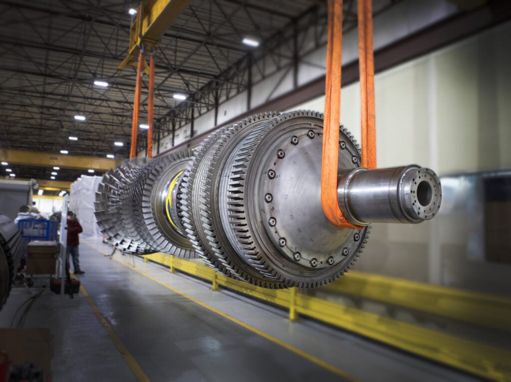
Alstom was contacted and was asked for a proposal for a new high-pressure/intermediate-pressure (HP/IP) rotor, manufactured by join welding and modifying and welding multiple stock rotor forgings (Figure 1). The replacement rotor proved to be more cost-effective as a permanent repair and faster than replacement of the entire turbine mono-block forging. Essentially, raw forgings were welded together to form the skeleton of a replacement rotor, but in a fraction of the time necessary for an original forging to be procured.
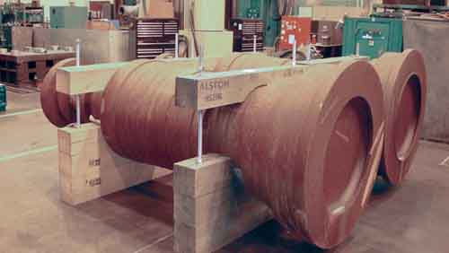
1. Two become one. The two forgings used for HP/IP rotor replacement were welded into a single rotor after rough machining to avoiding ordering a custom, long-lead-time forging. Courtesy: Alstom Power
Working with the Rotor
The rotor was next removed from the plant’s turbine casing before being transported to and received at Alstom’s repair facilities in Richmond, Va. Visual inspections were performed, complete measurements were taken, sample buckets were removed, and the rotor was blasted to clean and expose steeples.
Initially, blade rows 10 to 17 were to be refurbished, and new blades were to be manufactured for rows 1 to 9. However, it became more cost-effective, due to the condition of the components and shop scheduling, to manufacture all new rows of blades for rows 1 through 17.
The existing control shaft and overspeed trip assembly were nondestructively evaluated, and recalibration was performed on the overspeed trip assembly. Finally, low-speed balance-of-shaft components were completed.
The Replacement Rotor
The rotor forging sections were brought into the Richmond facility, set up and machined in the mill, and then the lathe was used to produce the join welding surfaces. After heat treatment of the welded rotor forging, the rotor’s wheels, dovetails, gland seals, and journals were completely machined. The coupling, balance weight holes, and steam balance holes were machined as part of the milling work (Figure 2).

2. Less is more. Forgings for the IP (shown here) and the HP sections were rough-machined prior to final weld preparation. Courtesy: Alstom Power
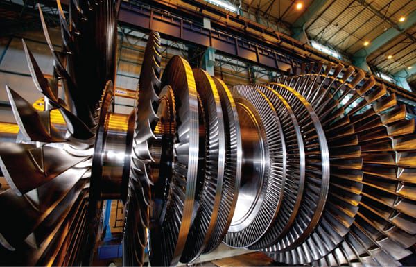
The rotor dovetails were then shot-peened. The newly manufactured blades were installed, shrouds were manufactured and installed, and shroud covers were machined. The rotor was first balanced at operating speed and then at 20% overspeed. The replacement rotor was rebuilt from scratch in only six months, and the unit was quickly restored to service (Figure 3).
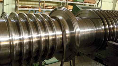
3. Final touches. Final machining of the complete rotor is in shown in progress. Courtesy: Alstom Power
During a six-month period, two turbine forgings were join-welded and modified by weld build-up to the configuration of the existing rotor. Not only was extensive machining and weld build-up involved, but instead of refurbishment, all 17 rows of new blades (a total of 1,492 blades) were also manufactured and installed to replace the HP and IP straddle roots for the turbine rotor.
Such a solution provides steam turbine owners significant potential cost savings when compared to normal delivery cycles for a new fully bladed turbine rotor; it also avoids considerable purchased power costs.
— Contributed by Mike Jirinec, proposal manager, and James Heeter, business development manager for Alstom Power.