Innovative Control Strategies Improve Boiler Dynamic Response
The more capable a power-generating unit is of reacting quickly to changes in load demand, the more profitably the unit can be operated. An improvement in load dynamics means that additional control response and capacity can be made available to the power grid. These characteristics are especially in demand in regions where a fast-responding unit can supply energy as ancillary services at a premium price.
However, the load dynamics of a coal-fired power plant unit are naturally restricted by the sluggish response of the steam generator, with its huge iron mass and the large boiler drum and pipe volumes where steam is stored. Several minutes will pass between a step increase in fuel flow to the coal mills and the steam generator’s response. Fixed times are required to pulverize the coal, transport it to the furnace, and then burn the coal, and those times must be considered in the design of a plant’s boiler controls. An increased firing rate will gradually produce an increased flow of heat to the steam generator and hence the water and steam. Only then can the mass flow of generated steam increase at a constant steam temperature.
Overcoming Inertia the Old-Fashioned Way
The capacitance in a boiler can be reduced by means of selectively using the areas where energy is stored in a power plant. The most common method of using stored energy is turbine valve throttling. Steam throttling is required when a defined unit load or steam mass flow is reached and the steam pressure upstream of the turbine is increased. If a fast increase in turbine output is required, the appropriate quantity of steam can be discharged by opening the turbine valve, thus immediately increasing generator power.
The disadvantage is that turbine valve throttling results in a continuous reduction of plant efficiency. Steam pressure also decreases quickly in the event of a rapid load increase as the stored steam is quickly removed from the boiler system. The fuel mass flow rate must therefore be increased disproportionately—first to counteract the rapid decrease in pressure and second to raise the pressure back to its setpoint or original value. The change in pressure and the resultant overfiring also put additional thermal stress on the boiler system.
In contrast, a nimble and quick-responding control system means that turbine valve throttling can be reduced, which results in a corresponding increase in efficiency and lower-stress operation of the power plant unit. Reducing boiler inertia also results in an increase in the stability of the controlled plant, quicker reaction to changes in load demands, and improved control loop response to faults. The economic benefits extend to a reduction in the cyclic control movements of the overall plant and of boiler stress in general.
The question for boiler controls designers is, How do you account for the boiler and other system inertia in your boiler control strategy? We propose a new approach that has been shown in testing to reduce actual boiler inertia by over 30%.
Case Study: Improvement Without Throttling
The following case study describes a control strategy that was successfully implemented in a German hard coal-fired unit that used part of the SPPA-P3000 family of solutions from Siemens Energy. The plant in which these new control strategies were implemented is rated at 750 MW gross and has an overall thermal efficiency of approximately 40%. The once-through boiler produces a rated 2,100 tons/hr (4.6 million lb/hr) of steam available at a pressure of 200 bar (2,900 psi) and a temperature of 535C (995F). The necessary firing rate is provided by six coal mills, each of which is assigned eight burners. All the burners of a mill are located on one level of the boiler. The six mills were equipped with a hydraulic grinding pressure adjuster in order to permit implementation of the extended control strategies.
The new control strategy was based on the SPPA-P3000 Fast Ramp solution to reduce boiler inertia in order to improve the unit’s load dynamics. In the initial phase of the project, the unit was equipped with a modern unit coordinated control structure. The second phase involved the installation of two innovative control modules: a center-of-fire control and an automatic control for mill grinding power designed to reduce the boiler time constant and consequently improve the unit load dynamics. Apart from the retrofit of grinding pressure adjusters for the individual mills, no process engineering changes were necessary.
Adjusting the Fireball Location. A number of boilers are equipped with tilting burners so as to make it possible to change the physical position of the fireball in the vertical plane of the combustion chamber. These tilting burners can be used to inject fuel upward or downward into the combustion chamber at a definable angle to the horizontal plane.
This adjustment is typically used to influence the amount of energy absorbed in the reheater. The higher the position of the fireball in the boiler, the more radiant heat is transferred to the reheater, and vice versa. If the center of the fireball is controlled such that the reheater injection mass flow is just equal to zero in steady-state operation and the reheater outlet temperature is at its setpoint, an overall increase in plant efficiency can be achieved.
Variation in the height of the fireball can also influence steam generation in the same way as lowering of the fireball causes more heat to be transferred to the evaporator. In the case of a once-through steam generator, the feedwater mass flow must also be increased so as to maintain the required steam enthalpy at the evaporator outlet at a constant level. If so, the increased feedwater mass flow immediately results in an increase in main steam mass flow. As a result, this performance measure can be used for a rapid increase in the steam generating capacity of the boiler. Temporarily lowering the fireball at the start of or during a load increase will result in an overall reduction of the boiler inertia or time constants.
With drum-type boilers, lowering of the fireball results in increased steam production and lowering of the drum level. Similarly, the boiler delay of drum-type boilers can therefore also be positively influenced using the center-of-fire control method.
Not all plants are equipped with tilting burners. However, if several mills supply burners on different levels, the position of the fireball can be influenced by trimming the outputs of the various mills. Similarly, level trimming can also be employed to influence the boiler time constant.
Operation of the coal mills is staggered by the center-of-fire control module during load ramps such that the mills on the lower levels are operated first, followed by those on the higher levels during an increase in load. This initially causes the fireball to be pulled downward so as to accelerate the increase in steam development. When the load increase stops, the fireball returns to its normal position. Figure 1 illustrates test data that show the staggered increase of mill outputs in response to a unit load increase.
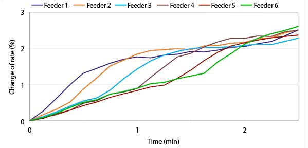
1. Innovative control strategies result in a staggered increase in feeder rates so as to improve unit dynamics. Source: Siemens Energy
Mill Energy Storage. The hydraulic adjustment of grinding power in the coal mills is another way to influence the dynamics of the boiler system. Increased grinding pressure, for example, immediately results in an increased grinding rate and consequently an increase in the coal mass flow following an increase in primary air. Based on the assumption that the feeder rate, or coal fed into the mill, remains constant, the level of coal in the mill will decrease. In essence, the mill is being used as an energy storage location, much like a steam drum, to support a rapid load increase.
During a load increase, feeder rate and grinding pressure are adjusted simultaneously. The level of coal is only lowered temporarily. It returns to the original value for the corresponding load point once the load ramp stops. The temporary utilization of stored energy brings about the desired reduction of the boiler reaction time. The reverse process occurs in the event of a load reduction. Figure 2 illustrates how the grinding pressure of the coal mills is adjusted relative to the load.
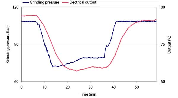
2. Innovative control strategies enable load-dependent adjustment of mill grinding pressure so as to improve unit dynamics. Source: Siemens Energy
The center-of-fire control is integrated as a module in the fuel distribution circuit. Distribution of the required firing load between the individual mills is no longer performed based solely on static criteria, as it now takes into account the dynamic criterion of the fireball position. Figure 3 illustrates how the SPPA-P3000 Fast Ramp solution integrates fireball control and mill grinding pressure control in the unit coordinated control structure.
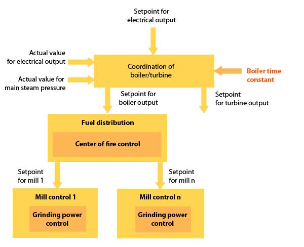
3. Integration of furnace fireball and grinding pressure control in a unit coordinated control system. Source: Siemens Energy
The module for controlling grinding power has now been integrated into the structure of the mill control, which also includes the modules for feeder control, primary air mass flow control, and classifier temperature control. The lower-level control structure thus automatically ensures a faster reaction capability for the boiler.
The new SPPA-P3000 unit coordinated control structure for controlling generator power and main steam pressure provides the basis for implementation of the new modules. The unit control module coordinates boiler and turbine and outputs the appropriate load setpoints. Implementation of the extended control strategies in the lower-level control loops ensures that the boiler time constant is reduced. The unit coordinated control structure simply has to take into account that the parameters of the model contained in it are adjusted.
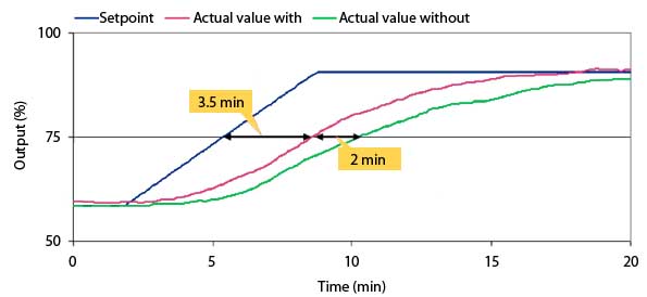
4. Marked increase in unit load dynamics is possible when a number of extended control strategies are implemented. Source: Siemens Energ
Figure 4 illustrates how the development of the electrical output of the case study plant for the same load ramps with and without the new control methods. In both cases output was increased without turbine valve throttling. The curves thus directly represent the boiler delay. It can clearly seen that these extended control methods made it possible to achieve a significant reduction in boiler inertia. In fact, the boiler time constant was reduced from the original 3.135 seconds to 3.85 seconds, a 37% improvement.
—M. Rech ([email protected]) is senior expert, process optimization; J. Rupp ([email protected]) is senior expert, process optimization; and K. Wendelberger ([email protected]) is director, process optimization for Siemens Energy.