Innovations in Air Heater Design Produce Performance and Reliability Improvements
Advancements in air quality control system design and sootblower technology have allowed the power industry to become more fuel flexible—but, in some cases, at the expense of plant reliability. Fuel blends with challenging mineral ash constituents can accelerate deactivation of SCR catalysts, NH3 slip, and/or sorbent injections for SO3 control that are the cause of boiler tube fouling, plugging, and/or corrosion of the air heater.
Air heater problems often lead to unit derates caused by lack of fan capacity, improper combustion temperatures, and/or unacceptable gas temperatures entering the stack. Higher-than-desirable air heater gas outlet temperatures can reduce the collection efficiency of electrostatic precipitators and have negative effects on the reliability of baghouses.
However, recent technical advancements in air heater design have been shown to successfully improve air heater and overall unit efficiency while reducing forced outages related to the air heater. In this article, we’ll address these technical advancements in terms of:
- Equipment operation and maintenance
- Mechanical component design
- Materials and coatings
Operation and Maintenance
Both air heater leakage and upstream air in-leakage from a boiler’s penthouse can significantly affect the thermal performance of a regenerative air heater, given its relatively large surface area (Figure 1). Most regenerative air heaters were originally designed for 6% to 10% air heater leakage and account for more than 10% of a unit’s overall thermal efficiency.
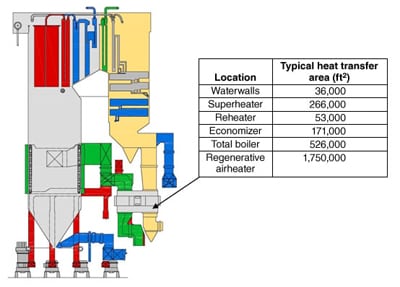
1. Heating surface comparison for a typical large utility boiler. Source: Stephen Storm Inc. and Paragon Airheater Technologies
Leakage occurs on the hot and cold ends of a regenerative air heater (Figure 2). However, most of the leakage often occurs on the cold end, where corrosion is more likely to occur due to the low air and gas temperatures, which produce larger clearances between the sealing surfaces. However, it’s also important to understand that air in-leakage upstream of the air heater can temper the incoming flue gas temperature while also increasing the volume of gas going through the air heater on a balanced draft unit.
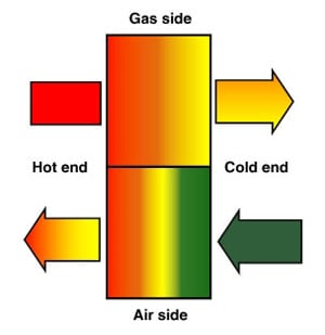
2. Regenerative air heater basic flow diagram. Source: Stephen Storm Inc. and Paragon Airheater Technologies
An air heater in poor condition will typically exhibit air in-leakage in excess of 15% to 20%. Considering this, correction of the gas outlet temperatures is required to determine the "no-leakage" gas outlet temperature. On a typical unit, each 30F to 35F is worth ~1% in unit efficiency.
Regenerative air heater design features, air-to-gas ratios, and air-to-gas pressure variations have a major impact on regenerative air heater performance. Note that the mechanical condition of the air heater and minimizing air-to-gas leakage is vital for the health of the air heater and overall plant performance. Any flue gas diluted with air leakage on the cold end of the air heater will lower the overall gas outlet temperature as well as change the gas temperature gradients downstream of the air heater outlet. Furthermore, it must be understood that high air in-leakage results in lower gas outlet temperatures and, when combined with S03, accelerated corrosion is likely to occur.
Numerous boiler operational parameters can influence SO3 formation. These variables are fuel sulfur content, ash content and composition, convective pass surface area, gas and tube surface temperature distributions, excess air level, firing mechanism, and coal fineness.
Leakage control in conjunction with the control of sulfuric acid (H2SO4) production is especially important when managing flue gas that is a byproduct of high-sulfur fuels. SO3 combines with flue gas moisture to form vapor-phase sulfuric acid at temperatures below about 600F. Therefore, any sulfuric acid in the flue gas can lead to significant problems, such as boiler air heater plugging and fouling, and corrosion in the air heater and downstream ductwork/equipment.
To prevent condensation of the SO3 (and thus limit formation of sulfuric acid) the exit gas temperature coming from the air heaters must be kept above the dew point of the sulfuric acid. The higher required exit gas temperatures translate directly into a loss of system efficiency, which imposes a significant heat rate penalty. However, the more SO3 is formed, the higher the dew point. The sulfuric acid dew point temperature depends on the SO3 and water vapor concentrations in the flue gas: Higher concentration of either species raises the acid dew point temperature.
Although a significant portion of the SO3 will condense on ash particles and be collected along with the fly ash, the noncondensed SO3 can have significant side effects. Excess SO3 leaving the stack can result in a noticeable "blue plume," which consists primarily of sulfuric acid that has condensed into tiny droplets. Those same droplets may also condense on the cold end of the air heater or in the downstream ductwork, causing corrosion and plugging.
In addition, excess SO3 can combine with ammonia slip from a selective catalytic reduction (SCR) system to form ammonium bisulfate (ABS), which has a notorious reputation for plugging air heater heat transfer elements. This ABS plugging also adversely affects the distribution of the air and flue gas by elevating air temperature differentials and gas leakage, as a result of the elevated pressure drop across the air heater. Essentially, the excess ammonia combines with excess SO3 and water vapor, which starts to condense on the air heater element surfaces at temperatures below about 450F (230C).
In some plants, to remove excess SO3, dry powder or water slurry mixes of alkaline sorbents (hydrated lime, limestone, magnesium oxide, sodium bisulfate, and trona) are sometimes injected upstream or downstream of regenerative air heaters. Though these chemicals are quite effective in adsorbing excess SO3 and reducing blue plume and corrosion, the effect of these sorbents on the air heater and its operation are still being evaluated.
Whether you are referencing burner performance, boiler performance, air heater performance and/or the air pollution control equipment, all of these components are influenced by their inputs with regard to their operational efficiency (see table). Variables such as the air heater gas outlet temperatures and velocity gradients, leakage/mass flow, coal fineness, sorbent particle sizing and distribution, excess air setting, calcium-to-SO3 molar ratio, ash content, and ash resistivity can have a significant effect on the air pollution control equipment.
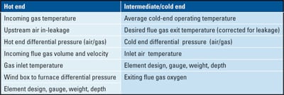
Important factors that affect air heater performance. Source: Stephen Storm Inc. and Paragon Airheater Technologies
Considering all of this, when evaluating the basic flow paths of a regenerative air heater (Figure 2), it’s important that the comprehensive interrelationships of all the previously noted variables be considered.
To properly assess air heater performance, the temperatures in and out of both sides of the air heater need to be known, as well as the oxygen concentrations before and after the gas side of the air heater. Velocity heads need to be measured, as feasible, to determine if there are any significant flow stratifications in the ducts. If so, the temperature and oxygen should be normalized on a flow-weighted basis. Furthermore, to perform a proper thermal heat balance, the air and gas flows before and after the air heater also need to be measured. This can be calculated as a function of static pressure, temperature, and velocity head measurement at each of the air heater inlet and outlet ducts.
Mechanical Component Design
There are many different options when it comes to choosing a heat exchange element design for an air heater. Each configuration has its own unique pressure drop and heat transfer characteristics. For example, an element configuration that is designed to achieve maximum heat transfer in a limited amount of space (depth) may also have a higher overall pressure drop than an element design that requires a greater depth to achieve the equivalent heat transfer.
Typically, the configurations with the lowest pressure drop per inch of depth also have a lower heat transfer rate per inch and require a greater depth of element for equal thermal performance. Although the end result of some element configurations can be an overall lower pressure drop while achieving the same amount of heat transfer, not all air heaters can accommodate the additional element depth that may be required without extensive modifications to the rotor. As an example, Figure 3 illustrates the varying element configurations options as a function of the theoretical gas temperature, based on a range of element thicknesses (in the direction of gas flow).
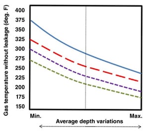
3. Example element configurations. Source: Stephen Storm Inc. and Paragon Airheater Technologies
Air Heater Leak. The main advantage of the regenerative air heater is that it is probably the least expensive heat recovery device that is able to operate reasonably well in the harsh environment of the flue gas exhaust stream from a fossil-fired boiler. A major drawback is the undesired leakages that are inherent to the design of the device.
It’s extremely difficult to seal these types of heaters due to the large temperature difference between their hot and cold ends (about 400F), coupled with the large diameter of the rotors. These opposing temperature gradients work together to produce a significant radial thermal expansion difference between the hot and cold sides of the air heater’s rotor after unit startup.
Due to this inherent thermal distortion, it’s not uncommon for the outer edges of a large air heater at operating temperature to experience a significant "droop" or "turn down." The distortion caused by this thermal turndown (which can be as much as 4 inches on some rotors) changes the gaps between the seals and the sealing surfaces as the rotor warms to operating temperature and is the most significant contributor to air heater leakage. This phenomenon must be accounted for when setting the seals at a cold state.
A considerable amount of additional air heater leakage can occur around the perimeter of the air heater through the bypass/circumferential seals. Figure 4 is a good representation of the various leakage paths through the air heater. In this diagram, the leakage through the circumferential seals (also called the peripheral seals or bypass seals) is depicted at the bottom.

4. Circumferential leakage through an air heater. Source: Stephen Storm Inc. and Paragon Airheater Technologies
Circumferential seals are located on the entire circumference of the air heater rotor, on both the hot end and cold end of the air heater. On the flue gas side of the air heater, all of the leakage through the inlet side circumferential seals will short circuit around the air heater (bypassing the heat transfer element) and exit through the downstream circumferential seals. This leakage results in a loss of enthalpy transfer into the element bundle and increases the temperature (and therefore the actual volume) of gas entering the induced draft fans.
On the air side of the air heater, leakage through the first set of circumferential seals will enter the annulus around the perimeter of the rotor, splitting in two directions. The leakage volume in each direction depends on the relative differential pressures of each path. A portion of the flow will continue in a straight path and exit through the second set of circumferential seals. The remainder of the flow will be directed around the perimeter of the rotor and exit into the exhaust gas stream (through the axial seals), and that volume will, in turn, exit the air heater through the gas-side cold-end circumferential seals.
Radial seal leakage represents the percentage of the gas flow downstream from the air heater that is the result of inlet air that leaks through the air heater seals into the gas outlet stream. The authors have observed radial leakage rates over 40% in some air heaters. Furthermore, leakage rates around 15% to 20% are often accepted as a "normal" condition, especially in older air heaters that have experienced physical distortion, wear, and erosion over time.
These high leakage rates places a significant burden on the boiler fans in order to move excess gas and air that serve no useful purpose. Because fans become much less efficient when they operate near full capacity, a 1% increase in fan volume can actually result in as much as a 3% increase in required fan horsepower. Therefore, even a small reduction in radial seal leakage can yield very large auxiliary power reduction.
Reducing Leaks. A cost-effective and simple method for reducing air heater leakage is replacement of the original equipment-type air heater seals with newer-design, high-performance, full-contact radial seals and progressively interlaced circumferential/bypass seals designed for flexibility under contact (Figure 5). Full-contact seals have demonstrated their ability to reduce air heater leakage by 50% or more from "as-is" levels in many air heaters when they have replaced original equipment-type seals.

5. The DuraPlus high-performance seal. Courtesy: Paragon Airheater Technologies
In comparison with an original design seal, which is in effect a rigid "proximity" air dam, the full-contact seal is constructed to maintain a continuous, but flexible contact with the sealing plate at all times, effectively eliminating the main path for radial seal leakage. These seals provide additional leakage reduction benefits because they are capable of maintaining full contact even when there is unevenness and distortion in the sealing surfaces (sector plates), as is commonly found in older air heaters. These "distortion gaps" can be a significant contributor to the high leakage rates found in most old air heaters.
The high-performance circumferential seals (DuraFlex) have a progressively interlaced structural design that provides both flexibility and resistance to tearing, which allows the seals to operate in contact with the perimeter sealing surface without being damaged, thus minimizing the gaps and leakage openings in comparison with original-style seals (Figure 6).
6. DuraFlex seal installed on a typical air heater. Courtesy: Paragon Airheater Technologies
Materials and Coatings
One method to reduce cold-end element corrosion is to coat the element with a state-of-the-art enamel that is formulated with nanoparticle additives. This nanotechnology is the result of a joint eight-year development project by the University of Bologna and SMALTIFLEX S.p.A., Modena, Italy, a Paragon Airheater Technologies partner.
Engineering materials, including coatings and, in particular, enamel coatings, often have a limited lifespan due to unavoidable degradation and unexpected damage from stress and strain. In order to overcome these issues, research in the field of self-healing materials, defined as a ”material where damage automates a healing response,” is currently an active field of study. This research is driven by the possibility that future materials may not have to be replaced, which would result in significant cost and efficiency savings. Vitreous enamel coatings are one of the materials that benefit from these research activities and are being used for high-performance applications.
Vitreous enamel coatings are a special class of ceramic-glass material used as coating for metal substrate. These coatings are characterized by high corrosion resistance (as much as 10 times higher than conventional stainless steel) and a high value of superficial hardness (from 600 HV to 800 HV); nevertheless, they are brittle in nature, and spalling phenomena can affect their in-service performance.
Development of a self-repairing enamel coating has also been driven by the need for enhanced mechanical performance when the coating is subjected to external static or dynamic (fatigue or impact) loads. Other types of materials have previously benefited from the autonomous repair concept to enhance their mechanical performance. In the case of polymer materials, two main strategies are being considered: induce a self-repair mechanism in a polymeric matrix when a polymer chain is broken and, using the inspiration of tissue self-healing, introduce a healing agent into the polymeric matrix. In the latter case, healing agents can be introduced in a polymeric matrix within microcapsules. The healing agent is released when cracks are able to open such capsules. After doing so, the interaction between the agent and particles of a catalyst that are introduced into the matrix can give rise to local polymerization effects suitable to bond the crack surfaces and stem crack propagation. A similar approach is under research where hollow glass fibers in a polymer-matrix composite are introduced into the coating. An agent stored within the hollow fibers is released when the fibers are broken, allowing both damage detection and in situ restoring effects.
However, these self-repairing coatings are not a vitreous material and, in particular, not one of them is a vitreous coating for metal substrate. Several additional problems remain to be solved in order to develop a self-repairing vitreous material, especially the intrinsic brittleness of the vitreous matrix and the coating adhesion to the substrate. These problems have been overcome by means of the proper combination of different materials manipulated at the nanoscale. In particular, the joint research collaboration of SMALTIFLEX and Bologna University has determined how to modify the enamel coatings through the addition of two metal oxides nanoparticles and one sub-micrometric repairing agent to produce a self-repairing enamel material without the brittleness or adhesion problems of a vitreous material.
The second innovation is reducing the number of particles that will stick to the heat transfer surface and plug the air heater using a no-stick enamel that is characterized by a reduced contact angle between a liquid drop and the enamel surface. Lab scale tests confirm that the no-stick enamel is less prone to plugging than conventional air heater elements.
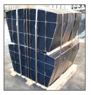
7. Vitreous enamel-coated elements/baskets supplied to Hawaiian Electric’s Kahe Point plant. Courtesy: Paragon Airheater Technologies
We expect that this innovation will produce further operational improvements, fewer outages for water-washing elements, lower long-term pressure drop in regenerative air heaters, and extended element life. These innovations are now beginning to appear in commercial products. Figure 7 is a photograph of a recent shipment of vitreous enamel-coated elements/baskets to a Paragon Airheater customer at Hawaiian Electric’s Kahe Point plant. We’ll report on the performance of these baskets in a future article.
—Stephen K. Storm is senior consultant of Stephen Storm Inc. John Guffre, PE is chief research scientist for Paragon Airheater Technologies (USA). Andrea Zucchelli, PhD is an assistant professor in the Mechanical Engineering Department at the University of Bologna.