Improving the reliability of turbine lube oil supply
Five years ago, San Onofre Nuclear Generating Station’s Unit 3 turbine experienced substantial damage after the supply of oil to its bearings failed. Because the turbine coasted down without oil after it tripped, its bearings, journals, and steam path needed extensive repairs. A follow-up investigation revealed lube oil system vulnerabilities that were subsequently corrected. The lessons learned might also improve your turbine-generators’ lube oil reliability, saving you many millions in lost revenues.
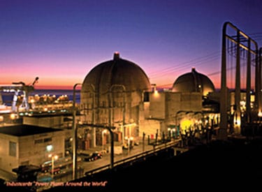
The San Onofre Nuclear Generating Station (SONGS) in northern San Diego County has one of the most beautiful locations of any power plant in the world (Figure 1). The plant, which is 75% owned and operated by Southern California Edison (SCE), consists of two nearly identical pressurized-water reactors rated at about 1,170 MW each. Units 2 and 3 (Unit 1 was mothballed in 1992) went on-line in 1983 and 1984. When the 1,800-rpm turbine-generator (TG) sets fed by the reactors’ steam generators were ordered from GEC (now Alston Power) in the late 1970s, they represented the largest nuclear prime movers ever built by the company.
|
1. Beautiful music. The San Onofre Nuclear Generating Station (SONGS) abuts the Pacific Ocean in northern San Diego County. Courtesy: Southern California Edison
|
Double your pleasure
The lifeblood of any piece of rotating machinery is lubricating oil (LO) supplied at the right cleanliness, quantity, pressure, and temperature under all anticipated operating conditions. An adequate supply of LO is especially important for turbine-generators as they coast down after a trip. For this reason, GEC’s common design practice in the late ’70s was to provide triple redundancy for LO supply—via a shaft-driven main lube oil pump and AC and DC motor-driven pumps during start-up and shutdown. However, the SONGS units were not equipped with shaft-driven LO pumps, for the following reason.
Under normal operating conditions, one AC motor-driven pump runs while the other remains on standby, ready to automatically start should LO pressure fall below 12 psig. If LO pressure falls below 10 psig, the turbine trip circuits are energized after a short delay, and the TG is tripped. The emergency, DC motor-driven pump, rated at about 65% duty, also is on automatic standby, ready to take over if both AC motor-driven pumps fail. No additional reliability features, such as gravity-feed systems or accumulators, were included in the original design (Figure 2). This double-redundant design served the plant well for many years, until early 2001.
|
2. Hidden flaws. A flow diagram of the original SONGS Unit 3 lube oil system. Source: Southern California Edison
|
Reversing the slippery slope
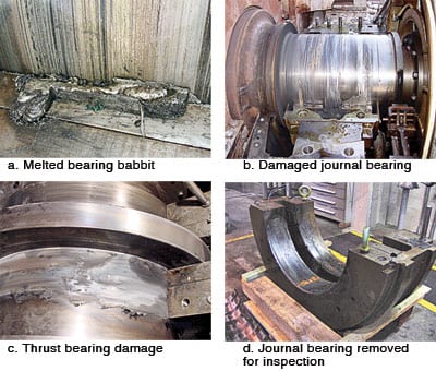
In February 2001 a circuit breaker feeding the DC emergency LO pump of Unit 3 failed to close after a loss of off-site power that resulted in a cutoff of electricity to the main oil pumps. Lacking a shaft-driven LO pump, the unit’s turbine-generator coasted down from full speed without lube oil. This caused significant damage to the TG’s bearing, journal, and steam path that required a four-month unscheduled outage to repair (Figure 3). Had the unit been equipped with a shaft-driven LO pump, the resulting damage would likely have been less extensive but still serious.
|
3. Hard stop. Loss of lube oil following a trip of the turbine-generator of SONGS Unit 3 caused significant damage to the turbine’s driveline journal bearings as it coasted down from full speed. The damage required a four-month outage for repairs. Courtesy: Southern California Edison
|
The first priority was to get the plant repaired and back on-line so plant design deficiencies could be assessed and action plans developed to correct them. A fault tree was developed using component failure data from industry-generic and SONGS-specific data sources. The results clearly demonstrated that existing LO and generator shaft sealing oil (SO) supplies were vulnerable to common-mode failure of all three pumps. Possible failures include random or seismic failure of electrical buses, spurious actuation of the fire-protection sprinkler system, loss of water for oil cooling, circulating water floods, and fires at various locations where all three pumps’ electrical cables are routed together.
The calculated mean time between failures (MTBF) for the as-supplied system was only 10 to 15 years—almost exactly what the plant experienced. After analyzing various design alternatives, SCE engineers segregated the major contributors to common-mode failure into two groups. The two groups of failure causes were addressed by the following steps taken to improve the reliability of the LO systems for SONGS Units 2 and 3.
Step One. These actions comprised relatively low-cost, high-impact improvements specific to the designs of the SONGS units. They included separating power sources, enhancing flood protection, and shielding electrical buses in the path of sprinklers. SCE engineers estimated that these modifications would improve reliability by increasing the MTBF of each system to 70 to 100 years. However, even this enhancement was deemed unacceptable, because there was still a greater than 50% probability that one of the SONGS units would experience a similar failure during the remaining life of the plant. SCE wanted to lower that probability to less than 25%, and the only way to meet that standard was to add reliability-improving features to the system—creating the need for Step Two.
Step Two. After considering various design alternatives, SCE engineers decided to add one more independent LO pump to each system. It was determined that doing so would increase the system MTBF to about 300 years and lower the probability of a repeat failure occurrence to well below 25% for the remaining life of the plant.
Delving into details
Very specific design objectives were identified once the overall system design requirements were determined. The key design objective was to ensure the reliability of LO supply under all credible normal and abnormal operating conditions, including the following scenarios:
- Loss of one or both AC pumps and the emergency DC pump.
- Transient response to the loss of a running AC pump.
- Common-mode failures such as fires, flooding, and seismic events
Lessons learned from the four-month outage also clarified the redesign objectives for the LO system:
- The modified system should not rely on activation of electrical or hydraulic control signals, because the use of such equipment reduces overall system reliability.
- The modified system should rely on passive features and avoid state changes in hydraulic, mechanical, or electrical equipment—such as the opening of non-return valves, pump start-ups, pressure-switch activation, etc.
- Eliminate or reduce the time required for the new, additional pump to reach full speed.
- Provide acceptable oil flows and pressure for all possible pump combinations during normal and abnormal operation.
An industry survey confirmed that the majority of large U.S. nuclear turbines have shaft-driven LO pumps with AC and DC-powered backup pumps. Although a typical, centrifugal-type, shaft-driven pump would protect the turbine at full speed, it would not provide total protection at lower speeds at the end of turbine coast-down—especially at SONGS, where the LO tank is significantly below the TG shaft centerline.
French connection
The SONGS team was surprised to find that, despite the number of reported loss-of-oil accidents, the industry in general still believes that shaft-driven LO pumps provide reliable turbine protection. The ability of a shaft-driven pump to deliver sufficient flow during TG coast-down depends on the type of pump. Shaft-driven, positive-displacement, gear-type pumps provide sufficient flow down to much lower speeds than typically installed, centrifugal-type pumps.
Some European original equipment manufacturers supply gravity-feed LO systems with LO tank(s) located above the turbine shaft line. Variations on this design include the use of one main gravity tank or individual tanks for each bearing. Though such an approach would have provided extremely high reliability, SCE ruled it out for cost and environmental reasons.
The operating experience of France’s state-owned nuclear utility, EdF, was found to be most relevant to the SONGS application. The standard EdF specification requires that at any given time, two independently powered pumps feed the LO and SO systems. Although there are many variations in EdF plant designs, the typical solution for the LO system is to use a shaft-driven pump with a continuously running motor-driven pump on standby. The backup supply is provided by independent AC and DC motor-driven pumps. At some of EdF’s older units the continuously running standby pump is driven by a DC motor; at newer units, the pump is AC-driven and powered from an independent battery through an AC-to-DC inverter.
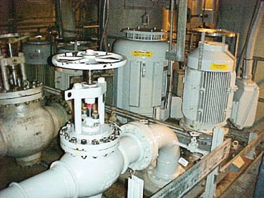
No bearing or seal-oil starvation incidents have ever occurred during the life of the more than 50 EdF nuclear plants operating with these schemes. At an EPRI turbine-generator conference in July 2001, it was reported that a total of five General Electric fossil-fueled TGs experienced LO starvation incidents in the first half of 2001 alone. Taking a page from EdF’s experience, the SONGS team chose to upgrade the site’s two LO systems with AC motor-driven pumps equipped with an adjustable-speed drive (ASD) and powered by an inverter. The new pumps were installed during 2002–2003 (Figure 4).
|
4. Better than new. A flow diagram of the updated SONGS Units 2 and 3 lube oil system. New components are shown in red. Source: Southern California Edison
|
Running in parallel
The new, dual power supply incorporates the inverters and ASDs. The ASDs allow SONGS operators to “fine-tune” pump performance, because the new coast-down pump (CDP) operates in parallel with the existing main LO pumps. Normally, the ASD is fed from the AC bus, with backup power available from the large independent battery bank. When the AC bus is lost, the uninterruptible power supply cuts in within about 2 milliseconds (Figure 5).
|
5. Belt and suspenders. The coast-down pump’s adjustable-speed drive and battery charger room. Courtesy: Southern California Edison
|
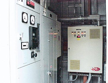
The power supply system is rated at 100 hp with a maximum output current of 258 amperes over the entire motor speed range above 400 rpm. The main design criterion for the battery bank was that it be capable of supplying two hours of reliable LO supply and six hours of SO supply if all other pumps become unavailable.
Running dissimilar centrifugal pumps in parallel is problematic at best, especially when the capacity and characteristic curves are so different. With a smaller CDP, the challenge was to provide stable oil flow and pressure when operating in parallel with the other AC pumps, while simultaneously supplying the minimum required oil flow when running alone.
The solution was to use a self-adjusting head/flow correlation by resizing the flow-restricting orifice on the main AC pumps’ discharge header. The criterion for orifice resizing was that one main AC pump running alone should be able to provide the required oil flow at a pressure above 15 psig. As new LO CDP flow is added downstream of this orifice, CDP flow is adjusted by turning down CDP speed to provide the minimum additional oil flow with two pumps running in parallel. At the same time, the CDP running alone at constant speed is capable of supplying the minimum LO flow required for safe turbine coast-down. During normal operation, both pumps work in parallel to supply lube oil to the turbine bearings (Figure 6).
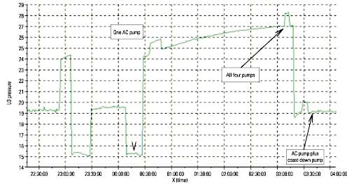
Self-adjustment of LO system pressure and flow, in accordance with system demand and pump characteristic curves, resulted in a slight system pressure increase to about 20 psig and a corresponding increase in overall oil flow. Because discrete flow data were not available, additional flexibility for the new pump design was included by incorporating the CDP speed-control feature plus bypass lines across the flow-measuring orifice. Test data for the upgraded LO system showed that the design provided the reliability and protection called for by the project’s design criteria (Figure 7).
|
7. Proving the design. SONGS Unit 2 lube oil pressure data for various pump combinations after the upgrades were completed. Source: Southern California Edison
|
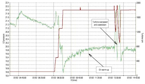
As a side benefit to the project, engineers became more knowledgeable about LO system performance—in particular, about the difference in flow demand between units, correlations between LO pressure and temperature, correlations between LO pressure and turbine speed, design margins, and more. This information is very valuable and certainly will be used on future projects (Figure 8).
|
8. Final exam. Lube oil pressure depends on turbine speed and oil temperature. Note that pressures remain within spec during overspeed and coast-down after a turbine trip. Source: Southern California Edison
|
—Fred Y. Simma is consulting engineer at the San Onofre Nuclear Generating Station; he can be reached at 949-368-2306 or [email protected]. Russell J. Chetwynd is the turbine generator engineer for Maintenance Engineering at the San Onofre Nuclear Generating Station; he can be reached at 949-368-9703 or [email protected]. Stuart A. Rowe is section leader, systems engineering at Alstom Power Service in Rugby, UK; he can be reached at +44 1788 531586 or [email protected].
The San Onofre Nuclear Generating Station (SONGS) in northern San Diego County has one of the most beautiful locations of any power plant in the world (Figure 1). The plant, which is 75% owned and operated by Southern California Edison (SCE), consists of two nearly identical pressurized-water reactors rated at about 1,170 MW each. Units 2 and 3 (Unit 1 was mothballed in 1992) went on-line in 1983 and 1984. When the 1,800-rpm turbine-generator (TG) sets fed by the reactors’ steam generators were ordered from GEC (now Alston Power) in the late 1970s, they represented the largest nuclear prime movers ever built by the company.