Improve Plant Heat Rate with Feedwater Heater Control
Meaningful, yet often hidden thermal performance losses occur in feedwater heaters. These controllable losses frequently occur because of poor-performing level controls. In this article, three issues related to feedwater heater performance are discussed. First, the large cost of a minute change in plant thermodynamic performance is quantified. Next, the physical difficulties of accurate level control are presented, as well as background on the important role that feedwater heaters play within the plant steam cycle. Finally, two short case studies are presented that quantify the cost savings that accrued to plants that successfully updated their feedwater heater level controls.
Cost of Heat Rate Deviation
Heat rate is a measurement used in the energy industry to calculate how efficiently a power plant uses the heat content of the fuel, expressed as the Btu of fuel heat required to produce a kilowatt-hour of electricity in units of Btu/kWh. The heat rate of just the steam turbine portion of the conventional power plant may also be calculated by dividing the energy content of the steam entering the steam turbine by the electricity generated. The turbine cycle heat rate represents the combined performance of the turbine, condenser, feedwater heaters, and feed pumps. The unit heat rate is found by dividing the steam turbine heat rate by the boiler efficiency.
If the plant operated without any losses, all of the fuel heat energy would be converted into electricity and the unit heat rate would be 3,412 Btu/kWh (the conversion factor between Btu and kWh at 100% efficiency). Although never achievable, the goal of the performance engineer is to find ways to continuously reduce the plant’s heat rate, because a lower heat rate (higher efficiency) reflects more cost-efficient operation of the plant.
Calculating the annual fuel cost associated with slight deviations from the plant’s target heat rate is always enlightening because the impact is much more profound than expected. For example, if a plant’s target heat rate is 12,000 Btu/kWh and the actual is a mere 0.1% higher than target or 12,011 Btu/kWh, what is the increase in annual fuel cost?
The change in annual fuel cost ($/year) for a 1 Btu/kWh deviation in heat rate can be calculated simply as HRD/BE x FC x CF x UGC x T, where:
HRD = heat rate deviation (Btu/kWh)
BE = boiler efficiency
FC = fuel cost ($/million Btu)
CF = plant capacity factor
UGC = unit gross capacity (kW)
T = 8,760 hours per year
Feedwater Heater Operation
Feedwater heaters are used to heat feedwater before the water enters the boiler. The higher the feedwater temperature, the less fuel is required to produce the steam used to produce electricity in the steam turbine. However, steam is extracted from different locations on the steam turbine to heat the feedwater, which increases the plant heat rate. The net effect of feedwater heating using extraction steam is a reduction in the plant heat rate.
The typical coal-fired power plant has six to seven stages of feedwater heating. The number of feedwater heaters is an economic balance between the added capital cost (the price of a typical feedwater heater is ~$1.2 million) and improved operating efficiency over the life of the plant (Figure 1).
.jpg) |
| 1. Efficient water heating. The feedwater heater uses steam extracted from the steam turbine to heat the boiler’s incoming water. The net effect of this process is improved boiler efficiency and a lower plant heat rate. A typical steam plant will have six or seven feedwater heaters. Source: Magnetrol International |
Feedwater heaters take advantage of the heat of condensation (energy available from the change from saturated steam to saturated liquid) to preheat water destined for the boiler. In simple terms, the shell and tube heat exchanger directs feedwater to pass through the tube side while extraction steam from the turbine is introduced on the shell side (Figure 2).
.jpg) |
| 2. Three-step process. A standard high-pressure feedwater heater has three sections: desuperheating, condensing, and the drain cooler or subcooling. Low-pressure heaters are similar in design, although they often can eliminate the desuperheating zone. This method of feedwater heating is far more efficient than relying on burning more fuel to bring water up to temperature. Source: Magnetrol International |
The feedwater heating process actually takes place in three distinct steps. First, the desuperheating zone cools the superheated steam to the point that the steam is saturated. Next, the condensing zone extracts the energy from the steam/water mixture to preheat the boiler feedwater passing through the tube side. Finally, a drain cooler is incorporated to capture additional energy from the liquid. The three heating processes all occur within a single heater.
Reliable Level Controls Required
Arguably the most important aspect to feedwater heater performance is precise and reliable level control under all operating conditions. Accurate level control ensures the unit is operating in the area of greatest efficiency (straight condensation) so that optimum heat transfer occurs while preventing undue wear and tear on the feedwater heater and other system components (Figure 3).
.jpg) |
| 3. On the level. Modernizing feedwater heater level controls allows operators to better manage controllable losses while significantly reducing maintenance costs. Torque tube displacers (shown in the photo) are common in the industry and one of the easiest to retrofit. Source: Magnetrol International |
Aging level instrumentation will introduce measurement errors that will reduce the effectiveness of a feedwater heater. In fact, errors of plus or minus 3 or 4 inches in water level are commonplace in the typical power plant. A feedwater heater experiencing suboptimal water levels will experience reduced heating effectiveness. In turn, the boiler controls must fire the boiler harder to replace the lost energy, burning more fuel, and increasing the plant’s heat rate. If the heater condensate level is higher than design, the active condensing zone is effectively decreased and tubes in the heater that should be condensing steam are instead subcooling the condensate, which is an energy loss to the system.
Some heater designs have the means to bypass the feedwater around the heater when condensate levels fluctuate to the extremes of its operating envelope. If condensate levels rise too high, there is a possibility of water induction into the steam turbine, which can have disastrous consequences. The feedwater heater may be mechanically protected from these extreme events, but the operating efficiency of the plant is certainly degraded.
A lower-than-acceptable level of condensate introduces excessive amounts of high-temperature steam to the drain cooler, which causes the condensate to flash to steam. The resulting damage to the drain cooler section increases maintenance cost and unscheduled downtime. In some cases, low heater levels can cause a mixture of steam and water through the heater, producing a reduction in heat transfer that also increases the plant heat rate.
Monitoring Performance
The primary parameters used to monitor individual heater performance are the feedwater temperature rise, the terminal temperature difference (TTD), and the drain cooler approach (DCA). Three important measurements can be taken that will provide information about the operating efficiency of a feedwater heater (Figure 4):
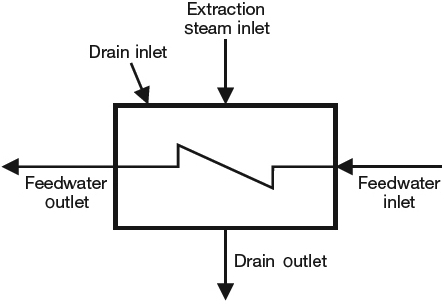 |
| 4.Performance measures. Feedwater performance is quantified in three ways: the feedwater temperature rise (the difference between the outlet and inlet feedwatertemperatures), the terminal temperature difference (the saturation temperature of the heating steam and the feedwater outlet temperature), and the drain cooler approach (the temperature difference between the drain cooler outlet and the feedwater inlet temperature). Source: Magnetrol International |
- Feedwater temperature rise is the difference between the feedwater outlet temperature and the feedwater inlet temperature. A properly performing heater should meet the manufacturer’s design specifications, provided the level controls are up to the task.
- Terminal temperature difference (TTD) provides feedback on the feedwater heater’s performance relative to heat transfer and is defined as the saturation temperature of the extraction steam minus the feedwater outlet temperature. An increase in TTD indicates a reduction in heat transfer while a decrease is an improvement. Typical ranges for TTD on a high-pressure heater with and without a desuperheating zone are –3F to –5F and 0F, respectively. The TTD for low-pressure heaters is typically around 5F. Steam tables and an accurate pressure reading are required to complete this calculation.
- Drain cooler approach (DCA) temperature is the temperature difference between the drain cooler outlet and the feedwater inlet temperatures. The DCA infers the condensate levels present within a feedwater heater. An increasing DCA temperature difference indicates the level is decreasing, whereas a decreasing DCA indicates a rise in level. A typical value for DCA is 10F.
Instrument-Induced Errors and Heat Rate
Although there are a number of physical anomalies that degrade heater performance, this section focuses on issues tied in some way to inadequate level control resulting in a below-design final feedwater temperature. The problems can range from something as simple as inaccurate or fluctuating readings across several instruments that leave the “real” level in question to those that justify taking a feedwater heater out of service. Regardless of the severity, the intention is to show the ripple effect that poor feedwater heater level control has on overall boiler and turbine cycle efficiency (increase in net unit or turbine cycle heat rate). Here are two primary sources of instrument-induced errors:
- Drift (mechanical or electronic). Drift is usually associated with aging instrumentation, moving parts, or is intrinsic to the design, such as with torque tube/displacers. With this technology, calibration between shutdowns is often necessary to achieve reasonable accuracy and prevent nuisance deviation alarms between multiple level transmitters. Responsiveness to rapid level changes can also be slow due to dampening effects fundamental to the principle of operation.
- Vulnerable measurement technology. Many measurement technologies are vulnerable to changing process conditions such as shifts in specific gravity and/or the dielectric constant of the media related to variations in process pressures and temperatures. Certain technologies also cannot provide accurate level from startup to operational temperatures without applying external correction factors, or the specified accuracy is only realized at operational temperatures. In general, technologies that fall in this category include differential pressure, magnetostrictive, radio frequency capacitance, and torque tube/displacers.
Lower-than-expected final feedwater temperature occurs when a feedwater heater is taken out of service due to unreliable level input to the control system or when the level is too high or low. If the condition is a result of high feedwater heater level, the operator would note a decrease in feedwater heater temperature rise, a decreasing DCA temperature difference, and an increasing TTD. The inverse is true if feedwater heater levels are too low. In either of the scenarios, risk of damage to hardware increases, heat transfer is impaired, and feedwater to the economizer is not at the required temperature. There are two probable operator responses to a low final feedwater temperature, neither of which is desirable:
- Overfire the boiler to increase temperature (level too high/low or out of service). This action will increase fuel consumption and emissions, as well as increase the gas temperature exiting the furnace. The increased gas temperature will increase the reheat and superheat sprays. Also, the steam flow through the IP and LP stages of the steam turbine will increase (when the heater is out of service), causing flashing and potential damage to the drain cooler section and possibly cause thermal damage to the tubes.
- Open emergency drains to lower level (level too high). This option causes an immediate loss of plant efficiency and can cause damage to hardware if water is inducted into the extraction line. The worst case occurs when the water is inducted back into the steam turbine, causing a possible catastrophic failure. The best case is that the turbine water induction protection (TWIP) trips the unit, shutting the heater down and causing expensive loss of production and other related costs.
Case Studies
The case studies cover two key topics relative to feedwater heater performance. The first details the increased annual fuel cost associated with an off-design final feedwater heater temperature at a 500-MW coal-fired plant. Although this particular situation does not fall into an extreme case warranting a heater bypass, it exemplifies how seemingly minor trade-offs in level control often have a large impact on unit heat rate (Table 1).
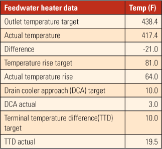 |
| Table 1. Case study 1. This table displays the results of off- design final feedwater heater temperature at a 500-MW coal-fired plant. Based on low outlet temperature, the heat rate rose 47 Btu/kWh, adding $243,000 annually to the plant’s cost of fuel. Source: Magnetrol International |
The second case study brings to light the day-to-day operational risks and costs that ineffective or aging instrumentation technologies have on the bottom line (Table 2). At this plant, the feedwater heaters were replaced in 2002, but the original instrumentation (1966-vintage pneumatic level controls and sight glass) was reused. The unreliable instrumentation caused feedwater heater level fluctuations that intermittently caused a bypass of all the LP heaters as part of the turbine water induction protection and placed the unit at risk of unexpectedly tripping offline.
.jpg) |
| Table 2. Case study 2. Cost justification for replacing aging level controls technology due to excessive bypassing of LP heaters. Source: Magnetrol International |
Note that the case studies do not take into account additional emissions cost, effects on boiler and turbine efficiencies, overfiring conditions, lost production, and other related factors, discussed earlier.
In both case studies, the return on investment for modernizing the instrumentation on the plant’s feedwater heaters fell in the 1.0- to 1.5-year time frame.
—Contributed by Donald Hite, regional manager Southeast Magnetrol International and Orion Instruments. View the POWER webinar on this topic on demand at powermag.com/webinars.