How Overcycling Induces Economizer Tube Failures

Today’s economic realities have forced many owners of combined cycle plants to transition from baseload to cycling operation—perhaps cycling the plant every day to catch emerging power sale opportunities. Many manufacturers have responded with equipment upgrades to meet this demanding service. In the case of heat-recovery steam generators (HRSGs), some manufacturers have raised their startup ramp rates to as high as 50 psi/min—but just because you can push them that far doesn’t mean you always should. HRSGs subjected to high cycling operating profiles are affected by thermal stress, water chemistry (notably dissolved oxygen), other operational considerations, or all of the above.
Like Goldilocks’ Porridge
HRSGs are unique in that the temperature differentials between the flue gas and water—particularly toward the evaporator gas exit—are quite low. To maximize thermal efficiency, water temperatures at the end of the economizer circuit run very close to the saturation temperature. The difference between the evaporator saturation temperature and the economizer outlet temperature is called the approach temperature (Figure 1).
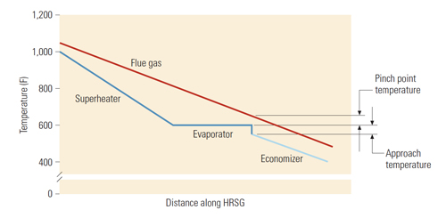
1. Pinch and approach points. The temperature differentials between the flue gas and water are quite low. To maximize heat transfer, water temperatures at the end of the economizer run should be very close to the saturation temperature. The schematic shows pinch and approach points for the HP superheater, evaporator, and economizer tube banks. Source: Deltak LLC
If the approach temperature is low—less than 10F—there is potential for economizer steaming. Since most HRSG economizers are either panels or serpentine style, steaming can create major problems. It may cause water hammer and vapor lock in some economizer circuits, causing high local velocities in some tubes and performance degradation of the entire economizer section. If the approach temperature is high—more than 10F above its “as-designed” value—the diagnosis may be economizer underperformance, one of today’s burning HRSG operational issues.
How Startups, Bad Designs Cause Stress
The steady-state thermal stresses in HRSG economizer tubes are normally quite low because the temperature differences between connected parts of the economizer are small. However, some HRSGs’ operating modes could produce very high stresses in the economizer—stresses that will ultimately lead to tube fatigue failure. It shouldn’t be a surprise that these stresses reach their maximum magnitude during startup.
In addition to material stresses and fatigue failure, there are other stresses related to HRSG designs and operating constraints:
- Economizer steaming is a persistent problem that occurs during periods of low flow—such as during startup or partial loading of the gas turbine. Steaming can also be the result of poorly designed or faulty baffles that allow gas to bypass them. Some plants have installed manual bypasses around the economizer during part-load operation with some success.
- Some early HRSG designs for baseload plants featured a HP/lLP economizer with a common header. Many of these plants have since split the HP and LP sections of the header to reduce thermal stresses during cycling.
- Unbalanced economizer flow distribution can cause another type of damage often seen in cycling HRSGs: tube-to-tube stress. Within the same tube bank, some tubes can be moving steam in the right direction and at the correct flow rate while others are moving either less steam in the same direction or the right amount of steam in the wrong direction.
Quenching: Another Stressful Event
Of the various cycling-related problems bedeviling economizers, pass-to-pass stress—which results when a hot economizer gets “quenched” by a slug of cold water—is the most common, best understood, and most readily corrected (see the sidebar “Preventing and Managing Cold Surges”). This type of stress can be damaging even at differential temperatures as low as 150F. Tube wall thickness is not a major factor, but tube bank geometry is, because poor geometry can produce inadequate flexibility and points of stress concentration.
During the early stages of an HRSG startup, there is no steam being produced in the HP evaporator and hence no demand for makeup water. With no demand for water, the feedwater control valve supplying the economizer is closed; hence, there is no water flow in the economizer. Under these conditions, the temperature of the gas entering economizer sections immediately downstream of the boiler/evaporator sections will be higher than the evaporator’s saturation temperature.
During a startup, if there is no water flow in the economizer before the HRSG begins to produce steam, temperatures within the economizer will approach the flue gas temperature. For an HP boiler, the temperature of the economizer panels can be in the range of 500F to 600F. In a multi-pressure boiler, where the HP economizer may be located behind an LP-boiler section, the temperature of panels may only get as high as 250F to 300F.
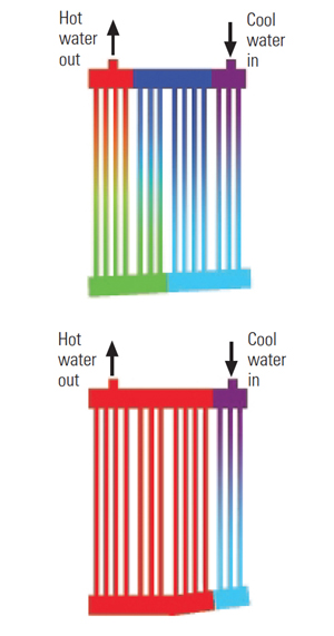
The economizers of all types of HRSGs are vulnerable to the stresses of economizer quenching. The maximum stresses occur in different places (see the sidebar “Fatigue Damage to HRSG Tube-to-Header Joints”), depending on the style of HRSG construction and the means used to restrain the part’s thermal growth, some of which are illustrated in Figures 2 through 5. The transient events that cause the thermal growth that creates the stresses may be short-lived, but they nonetheless shorten the economizer’s available fatigue life each time they occur.
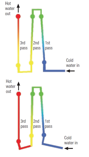
2. Single-row, panel-style construction. This schematic shows shrinkage of the first two passes as the cold surge reaches the end of the second pass. This motion puts stress on the incoming line and the panel-to-panel jumper pipes. Source: Deltak LLC
3. Multi-lateral pass style of construction. Shrinkage of the first pass as the cold surge reaches the end of the pass creates loads in the tubes in the first and second pass.
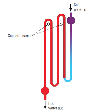
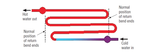
4. Return-bend style. This style of economizer is supported by hanger beams under the upper return bends. When the first-pass tubes shrink, they try to lift the remaining passes off their hanger beam, inducing stresses. Source: Deltak LLC
5.Vertical flow. A vertical gas flow HRSG with a horizontal water flow serpentine circuit will experience shrinkage of its first-pass tube when the cold surge reaches the end. When the first-pass tube shrinks, it will try to pull the entire array toward itself. Source: Deltak LLC
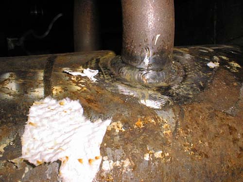
6. Fatigue failure in tube-to-header joints can be almost invisible to the naked eye. Courtesy: Deltak LLC
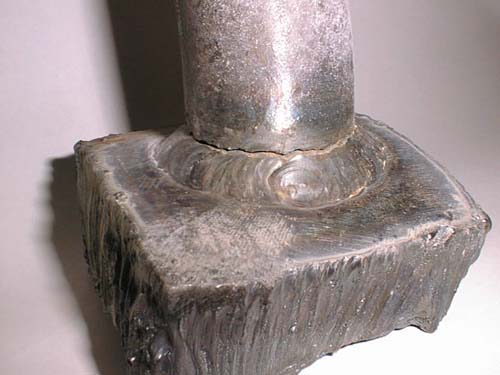
7. An Inside view. The same fatigue failure with the joint opened up to illustrate its location and surface features. Courtesy: Deltak LLC
Regardless of the style of weld used in the joint, testing shows that the fatigue fracture always occurs at the toe of the fillet weld. Finite element analysis corroborates this finding. Figure 8 shows the results of a typical finite element analysis of a full-penetration, tube-to-header weld. The peak stress is at the toe of the fillet, the very location where experimental fractures always occur. Even when a defect is embedded in the root of the weld, both finite element analysis and fatigue testing show indicate that the peak stress occurs at the toe of the fillet weld.
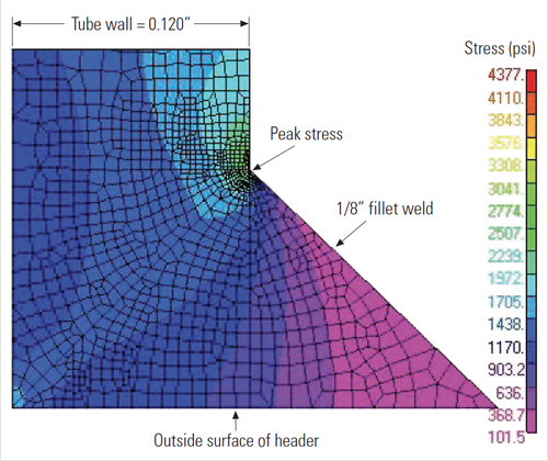
8. Where the failures are. Finite element analysis indicates that the fatigue failures of tube-to-header weld joints are always at the top of the filet—where the peak stresses are. Courtesy: Deltak LLC
Very little information about stress intensification factors for tube-to-header joints can be found in the published scientific literature. To fill this void and allow accurate estimates of HRSG fatigue life, Minneapolis-based Deltak LLC built a machine for full-scale fatigue testing of typical HRSG tube-to-header connections. During the past two years, this machine has been used to evaluate five different tube-to-header weld configurations:
- Full-penetration welds
- Full-penetration welds with a precisely blended fillet radius
- Full-penetration welds with an incomplete root pass
- Partial-penetration welds
- Fillet welds
Hyperactive Control Valve
In a system that is operating properly, there will be only one cold surge event during each startup. So even if a plant is started up 300 times a year, it would experience no more than 300 of these extreme thermal events annually. It is indeed possible to design an economizer to withstand cold surges of this number and frequency.
However, if the system is not operating properly, all bets are off. For example, should the economizer’s feedwater control system malfunction, the feedwater control valve might oscillate between fully open and fully closed many times per hour. Under these conditions, if the HRSG economizer was designed for 300 cold surge cycles per year, it would see a year’s worth of fatigue cycles in just 30 hours if there are just 10 full swings in control valve position per hour.
Quenching from excessive numbers of cold feedwater surges has been identified as the root cause of economizer tube failures in several HRSG systems. For example, a few years ago a Louisiana cogeneration plant reported that it had been experiencing economizer tube failures in the same general area every two to three months. All of the failures occurred in a cluster of tubes directly opposite an inlet nozzle of a panel near the end of the economizer circuit. At this point in the circuit, cold feedwater is brought into the economizer to reduce temperatures and avoid steaming in the economizer at low gas turbine load.
The Louisiana plant was running its gas turbine at the low end of its design range due to low demand by the steam host. At low turbine exhaust flows, economizers tend to operate at higher temperatures, and at those temperatures the approach temperature is lower and the potential for economizer steaming is higher. What running the gas turbine at low load did was create a need for a constant flow in the bypass circuit, to cool the last passes of the economizer and raise the approach temperature.
Discussions with the operators revealed that the control valve for the bypass cooling water had been operating erratically for some time. It would drive itself to either the full-open or full-closed position, at which point manual intervention by the operator was required. When the valve was returned to automatic operation, its control response would eventually degrade again to the full-open/full-closed behavior.
Each time the control valve went through a full-open/full-closed cycle, a surge of cold water would be introduced into the warm economizer. The result was a control system that caused excessive cycling of the feedwater control valve. The excessive cycling eventually led to premature fatigue failures in the economizer.
Close the Loop
Note that in a case such as this, where excessive cycles have been inflicted on a piece of equipment, eliminating the source of excessive cycling does not immediately result in fewer failures. The affected tubes may have already suffered a high number of cycles, and although the rate of cycling is reduced by the corrective action, the tubes may have already lost a large portion of their fatigue life.
Experience with other HRSGs and discussions with plant operators have revealed that excessive feedwater valve cycling and associated tube failures due to malfunctioning controls happen more often than would be expected. If your HRSG is having failures in its economizer tubes, one of the factors that should be investigated is the functioning of the feedwater flow control. If the control valve cycles between open and closed more than once during a startup or is cycling open and closed during steady-state operation, it will create excessive thermal cycles and accelerate the rate of fatigue damage in the economizer.