Global Monitor (March 2007)
Winter storms ravage Nebraska grid
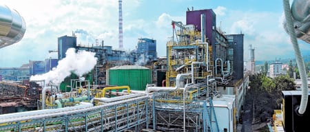
No state in the U.S. was slammed harder by this winter’s weather than Nebraska. Storm after storm swept across the Cornhusker State, devastating the transmission system of Nebraska Public Power District (NPPD), reducing generation from NPPD’s largest power plant (the 1,365-MW coal-fired Gerald Gentleman Station), and making line repair difficult and dangerous.
A huge ice storm at the end of December knocked out 824 miles of NPPD’s 4,000-mile transmission and distribution grid. About 160 miles will have to be rebuilt from the ground up (Figure 1).
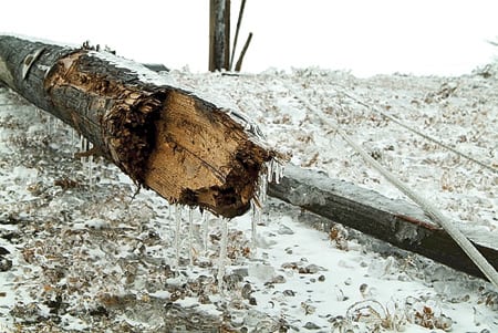
1. Cold snap. End-of-the-year ice and wind storms devastated Nebraska Public Power District’s transmission network, isolating its largest power plant. Courtesy: Nebraska Public Power District
"The storm basically cut our statewide transmission system in half," said Ron Asche, CEO of NPPD. "That damage is visible to anyone driving past the downed power lines. What many don’t realize is that we also had to reduce [generation] at our largest power plant. We have had to replace that power by running higher-cost plants and buying electricity on the spot market. This may add millions of dollars to our operating costs for 2007."
As temperatures rose after the ice storm and service restoration crews began to assess the damage and get power flowing again (Figure 2), Nebraska was struck by a windstorm with gusts topping 50 mph. Crews worked through the dangerous conditions to restore power as quickly as they could, and much—but not all—of the statewide power system was working again within about a week.
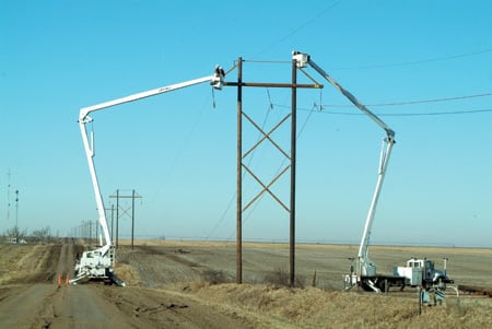
2. Adding insult to injury. NPPD crews had to face high winds as they worked to rebuild the statewide transmission and distribution system. Courtesy: Nebraska Public Power District
NPPD estimates it will pay $40 million for replacement power from the date of the storm through May of this year. The wholesale generation, transmission, and distribution utility guesses that another $140 million will be needed to repair the damage to its electrical system. NPPD’s reconstruction manager, Barry Campbell, said, "In reality, we are building from the ground up in some places." He described the situation as "a larger-than-life jigsaw puzzle we need to put back together before summer."
On January 7, President Bush declared scores of Nebraska counties federal disaster areas, making public power distribution utilities in them, and NPPD, eligible for federal aid. NPPD said it expects to cover the transmission reconstruction costs not covered by the federal assistance by issuing long-term debt, over a 20- to 30-year period.
But the cost consequences of cutting generation at Gerald Gentleman Station, which supplies about half of NPPD’s power, may require the utility to consider a rate increase. "The sooner we can start generating more power at Gerald Gentleman Station and transmitting it over the rebuilt lines, the better it will be for our customers," said Asche. "But no utility can rebuild more than 160 miles of transmission lines overnight, and it is too early to determine what impact [the rise in] our operational costs will have on us overall."
Images and video of the storm damage are posted on NPPD’s web site (www.nppd.com).
Waste-fired plant coming to Arizona
A power project capable of converting forest or paper waste into as much as 24 MW of electricity is well under way in eastern Arizona.
The Snowflake White Mountain Power plant has been designed to burn woody waste material from any of three sources—thinning of surrounding National Forests, small trees burned in the 2002 Rodeo-Chediski wildfire (the largest in state history), and waste from nearby sawmills. It also will burn waste from a nearby paper mill that produces 250 tons of waste paper fibers daily and sends them to a nearby landfill. Soon, the paper waste will instead be sent through a series of presses to lower its moisture content and then to the power plant’s boilers.
The plant is expected to be commissioned late this year, when it will begin supplying Salt River Project (SRP) and Arizona Public Service (APS) under long-term power-purchase agreements. The $53 million project is being developed by NZ Legacy LLC, a private company that began life in 1866 with a state charter to develop a railroad line. The Snowflake project, in the town of the same name, was the winning bidder in a 2004 SRP request for proposals for 10 MW of biomass power.
Scott Higginson, executive VP of NZ Legacy, told the Associated Press, "This project is about environmental protection and creating electricity in an environmentally safe and renewable fashion." According to Higginson, SRP has committed to buy 10 MW for 15 years, and 20 MW in each of the final five years of its 20-year contract. APS is buying 10 MW for 15 years.
NZ Legacy said that the plant will be powered by a Babcock & Wilcox bubbling fluidized-bed boiler (Figure 3) that has been specifically designed to accommodate the waste fuel specs. The developer explained that the plant’s reuse of components (including conveyors and screw presses) from an idled paper facility in Houston will improve its economics.
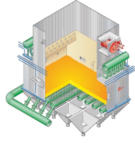
3. B&W bubbler. The open bottom of the lower furnace of Babcock & Wilcox bubbling fluidized-bed boilers offers a clear path that eliminates debris without creating dead zones in the bed, says the company. Courtesy: Babcock & Wilcox
Another economic plus, said NZ Legacy, is the new plant’s ability to share the paper mill’s 40-MW substation. Only 3 to 4 MW of its capacity are now being used, and the substation’s interconnections, relays, and switches are all less than four years old. An interconnection with APS is already in place. Furthermore, natural gas is already available for start-up needs, and the paper mill has both a state-of-the-art control room and monitoring equipment and company-owned rail service and trucking contracts for fuel handling.
The Snowflake plant has caused some concern for environmentalists. The AP quoted a local Sierra Club officer as expressing doubts. "We certainly wouldn’t want to see Arizona put all its eggs in the biomass basket," said Sandy Bahr. "I don’t think that biomass plants are really a good energy solution per se because clearly there are still issues with emissions."
Wärtsilä lands jobs in Azerbaijan, Sweden
Finland’s Wärtsilä Corp. late last year landed two significant power plant equipment contracts, one in Azerbaijan and the other in Sweden.
In Sweden, the company will supply and install the equipment for a biomass-fueled combined heat and power (CHP) project for city of Halmstad, on the southwest coast. The KVV-Turbingatan project will have a thermal output of 19.3 MW and an electric output of 3.2 MW. The plant is scheduled to supply heat at the end of this year and electricity at the end of 2008.
Wärtsilä’s BioPower 5 technology (Figure 4) will be used to burn wood residue from various sources in the area. It will deliver hot water primarily to Halmstad’s district heating network but will send some to local industry as well. The electricity will be fed to Sweden’s national grid. Halmstad has a population of about 88,000.

4. Waste not. Wärtsilä’s BioPower 5 technology converts wood waste to heat and electricity efficiently and with few emissions. Courtesy: Wärtsilä Corp.
According to Wärtsilä, this will be the fourth CHP plant in Sweden powered by its BioPower 5 concept. The others are in Trollhättan, Mark, and Motala. A BioPower 2 plant is operating in city of Tranås. Wärtsilä says BioPower technology burns biofuels efficiently, with low emissions of NOx and carbon monoxide.
The BioFuel plants operate on a closed steam-feed water system separate from the district heating water system, Wärtsilä explains. Steam is generated in a watertube boiler and supplied to a back-pressure steam turbine that drives an alternator. The turbine’s exhaust heats the district heating water, and its condensate is returned to the boiler as feedwater. Because the plants are modular, they can be built, delivered, and installed quickly.
In Azerbaijan, the state-owned electric company has contracted with Wärtsilä for a 300-MW, multifueled power plant using reciprocating engines. It will be sited about 30 miles south of the capital of Baku. The plant will have 18 generating sets powered by 18-cylinder 50DF internal combustion engines, each rated at 17 MW. The engines will normally run on natural gas but can switch to No. 2 or No. 6 oil if the gas supply is interrupted.
In addition to supplying the gensets, Helsinki-based Wärtsilä also will provide the power plant design, other major equipment, all building materials, and supervision of equipment installation. The company will also train operations and service personnel from AzerEnerji (the customer, Azerbaijan’s national utility) for two years.
The order is Wärtsilä’s sixth sale to AzerEnerji. In 2005 the utility bought five plants with a total generating capacity of 450 MW, all based on the company’s 34SG gas-fired gensets. All were commissioned in 2006. The same technology powers Wärtsilä’s largest gas plant for decentralized service, a 115.6-MW project at a gold mine in northeastern Nevada (Figure 5).

5. Gold standard. A plant powered by Wärtsilä gas-fired gensets provides 115 MW of capacity at the Barrick Goldstrike gold mine near Elko, Nevada. Courtesy: Wärtsilä Corp.
Yet another controversial LNG project
A proposal to build a floating liquefied natural gas (LNG) terminal in Long Island Sound is drawing opposition in New York and Connecticut despite having received two regulatory endorsements in Washington.
The Broadwater Energy LNG project, a joint venture of TransCanada Corp. and Shell, would sit at the widest portion of the sound, about 9 miles off New York’s coast and 11 miles from Connecticut’s. The 1 billion cubic feet per day project would permanently attach a ship-like vessel, known as the floating storage regasification unit (FSRU), to a mooring tower embedded in the sea floor. The FSRU (Figure 6) would measure 1,215 feet long and 22 feet wide—as big as the Queen Mary II—and rise 82 feet above sea level.
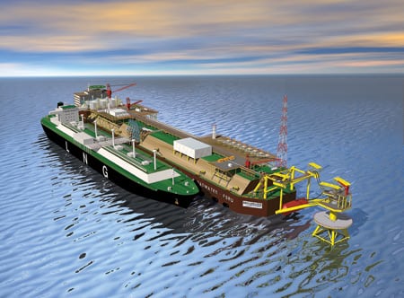
6. Boon or bane? This artist’s conception shows how the Broadwater Energy LNG project planned for Long Island Sound would receive liquefied gas from tankers, regasify it, and send it by pipeline to the mainland. Courtesy: Broadwater Energy
Typically, two to three LNG carriers per week would deliver liquid cargoes to the FSRU. The regasified product would move by undersea pipeline to the Iroquois Gas Transmission System pipeline onshore.
The project has generated considerable controversy on both sides of the sound. In New York, Suffolk County is opposing the project. Newsday commented, "Opposition to the proposal, often irresponsible, is fierce and likely to get fiercer, and its object would be highly visible—an enormous floating vessel filled with natural gas tethered nine miles from Wading River."
In Connecticut, some 700 protesters jammed a mid-January Federal Energy Regulatory Commission (FERC) public hearing on the project. Among them was Connecticut’s Democratic Attorney General Richard Blumenthal, who has made his reputation by opposing energy projects in or near the Nutmeg State. Blumenthal has asked the Federal Aviation Administration to establish a no-fly zone over the project, a unique approach to trying to stop it. "We have fought them on the water and the beach and now we are taking it to the air," he said.
But the Coast Guard has already given Broadwater a thumbs-up, and a draft Environmental Impact Statement by FERC last November said the project poses no insurmountable environmental obstacles. Many observers expect FERC to approve it this spring.
That doesn’t mean the project will get built. Newsday noted that Broadwater also must be approved by newly seated New York Democratic Governor Eliot Spitzer because it is closer to his state’s side of the sound. Spitzer, the newspaper wrote, "has wisely resisted political pressure, based on reckless assumptions, to make a hasty call on its merits."
FERC Chairman Joseph T. Kelliher said at the Connecticut meeting, according to the Westport News, "There’s more than one decision-maker. If we disapprove a project, it can’t be built. But we’re not the only body that has to approve an LNG facility."
Siemens lands two-gasifier order in China
Siemens Power Generation has won a contract to supply two entrained-flow gasifiers with a thermal capacity of 500 MW each to a subsidiary of China’s largest coal producer. Siemens says the contract is worth about $39 million.
The contract is with Shenhua Ningxia Coal Industry Group Co. Ltd., a subsidiary of Shenhua Group, China’s largest coal producer. The gasifiers will be the heart of the Shenhua Ningmei project in Ningxia Province in northwestern China to produce 830,000 tons per year of dimethyl ether, which can be used as a substitute for natural gas, propane, and liquid transportation fuels.
Klaus Voges, president of Siemens PG, said, "The order is an important reference for our new generation of gasifiers in the 500-MW class. [It will] strengthen our position in China, the world’s most important market for coal gasification, as an environmentally friendly technology of the future."
Siemens operates an extensive gasification research center in Freiberg, Germany (Figure 7), and has been developing the technology since 1975. In mid-2006, Siemens bought the gasification activities of Sustec AG, a privately held company based in Basel, Switzerland. Sustec had developed some significant gasification technologies and markets.
7. A refinery? Not. Siemens Power Generation operates this extensive gasification test facility in Freiberg, Germany. Courtesy: Siemens Power Generation
China, now the world’s second-largest energy consumer, has major coal reserves, on the scale of the U.S. and Russia. According to Siemens, coal currently satisfies 76% of China’s primary energy consumption and fuels 70% of its electricity generation.
"The Shenhua Ningmei DME project is the first major coal gasification plant contract that Siemens has been awarded since the acquisition of Sustec," said Voges. Although Siemens has traditionally been focused on technology for producing electric power from coal, the German company’s gasification technology also can be used to produce synthetic fuels and chemical products, including pure carbon. Siemens offers commercial gasifiers with thermal capacities ranging from 5 MW to 500 MW.
IndyCars drink nothing but ethanol
This year, IndyCars are running on a renewable fuel. When the open-wheel racers raced at Daytona International Speedway on January 31 and February 1 to preview the upcoming season, they all burned 100% fuel-grade ethanol from Renova Energy’s plant in Torrington, Wyo. (Figure 8).

8. Fuel for torque. The fuel for all contestants in the 2007 IndyCar racing series, 100% ethanol—known as "white lightning" by the earliest U.S. auto racers—will come from Renova Energy’s plant in Torrington, Wyo. Courtesy: Renova Energy
The 17-race IndyCar series officially opens March 24 in Miami and runs through September. The premier event will be the venerable Indianapolis 500, on May 26.
In the 2006 season, IndyCars burned a mixture of 90% methanol, produced from natural gas, and 10% ethanol, produced from corn. Prior to that, they ran exclusively on methanol. Both are forms of alcohol. Humans can drink ethanol, but not methanol.
The Ethanol Promotion and Information Council (www.drivingethanol.org), an industry lobbying group, contracted with Renova to supply about 120,000 gallons of the fuel for the IndyCar Series this year. The company produces 10 million gallons of ethanol annually and has a new, 20,000-million gallon/year plant planned for Heyburn, Idaho.
Les Mactaggart, senior technical director for the IndyCar series, said that extensive tests of ethanol in the new 3.5-liter, 650-hp Honda Indy V-8 have shown impressive results. He added that the transition to the all-ethanol fuel "has been flawless." Fuel from Renova’s Wyoming plant will be shipped to Indianapolis and stored at Superior Solvents and Chemicals’ warehouse, which can take 30,000 gallons. Superior will be in charge of loading tankers and distributing the fuel to each IndyCar event during the season.
The Ethanol Council’s Tom Sluneka said, "Ethanol is not only an ideal solution for high-performance IndyCar Series cars [Figure 9]; consumers can expect improved performance and environmental benefits as well with enthanol-enriched fuel. From the speedway to Main Street, the partnership between the ethanol industry and the Indy Racing League will deliver stunning results."

9. Ears to the ground. The corn-powered cars in the 2007 open-wheel circuit will run their feature event in May at the Indianapolis 500, on the Brickyard. Courtesy: Indy Racing League
Dan Schwartzkopf, Renova Energy senior VP, called the move to ethanol "the most significant fuel change in open-wheel racing in 40 years. This is a groundbreaking achievement."
New Otto/diesel engine to debut in Russia
MAN Diesel of Augsburg, Germany, has gotten the first order—from Gazprom subsidiary Mosoblenergogas—for its new 32/40PGI natural gas–fired engines. Two engines and a heat-recovery boiler will serve as the core of a CHP project in Moscow planned for completion next year. PGI stands for "performance gas injection," a new, high-energy ignition scheme that, according to MAN, affords users the best features of both diesel and Otto internal combustion technologies.
Otto cycle technology is superior for spark ignition, whereas diesel is better for engines that compress fuel. In a press release, MAN says the new engine (Figure 10), which has no spark plugs, "combines for the first time the advantages of a diesel engine, such as high power density and high efficiency, with the low noxious emissions of a gas engine."
The new engines come in 12- and 18-cylinder versions with power output ratings of 5 to 8 MW. An early production model has been powering a CHP plant at MAN’s Augsburg headquarters since 2005, delivering electricity to a foundry’s melting furnaces and thermal energy for space heating and production processes. MAN introduced commercial versions of the engine at a European trade fair last May.

10. MAN Alive. MAN diesel says its new engines combine the best of both diesel and Otto cycle (spark-based) technologies: the power of the former and the lower emissions of the latter. Courtesy: MAN Diesel
POWER digest
News items of interest to power industry professionals.
An Alstom trifecta. Three big deals—two in Europe and one in Africa—made the last quarter a good one for Alstom. First, the French company won a contract worth $103.5 million from Union Fenosa Generación, S.A. to retrofit the boiler of the 550-MW Meirama coal-fired station near La Coruña, Spain. The project will be the largest ever to fuel-switch a unit, from lignite to bituminous coal. As local lignite reserves deplete and emissions regulations tighten, the plant will increasingly burn low-sulfur bituminous coal from Indonesia.
According to Alstom, the most interesting part of work will entail replacing existing lignite burners with tilting, tangentially fired burners. The new burners will afford improved control of the furnace fireball and therefore internal heat exchange. Greater fuel efficiency and flexibility are the expected results.
Next, Alstom—as leader of a consortium—won a contract worth $103 million from the Egyptian Electricity Holding Co. for two 350-MW steam turbine-generators and condensers. Alstom’s share of deal is pegged at about $76 million. Under the contract, Alstom also will install the units and provide technical assistance and training during commissioning, testing, and start-up. The customer’s Cairo Electricity Production Co. unit will operate both units, which will be fueled primarily by natural gas. The project is part of Egypt’s plan to modernize its infrastructure and is supported by the World Bank’s 2003 Infrastructure Action Plan.
Finally, Alstom announced that it has signed a contract worth over $41 million to replace four 500-MW generator stators at Scottish and Southern Energy‘s Fiddler’s Ferry plant in Warrington, UK. According to the company, the state-of-the-art replacement stators will use water-cooled and stainless steel materials to increase unit output. The stators will be delivered between June 2009 and March 2010.
Entergy buys Dynegy peaker. An Entergy Corp. subsidiary is buying a 322-MW natural gas–fired peaking plant in Louisiana from Dynegy Inc. for about $57 million. Entergy Gulf States has signed an agreement to buy Dynegy’s Calcasieu plant, a simple-cycle facility powered by Siemens turbines. The two units at the plant went into commercial operation in 2000 and 2001. The deal is likely to close in early 2008. Entergy says it plans some $6 million in upgrades at the plant. Counting $3 million in transaction costs, the total capital cost of the project works out to about $205/kW.
J. Wayne Leonard, Entergy’s CEO, noted that the plant’s "location in southwestern Louisiana is clearly advantageous because of its close proximity to large customer loads with large potential load swings. The quick-start nature of Calcasieu allows it to be dispatched with short notice and will be beneficial due to limitations on the ability to import power into the region."
DOE fossil budget seeks 33% hike. The Bush administration has proposed major increases in funding for coal technology research and development in the Department of Energy’s fiscal year 2008 budget. However, veteran observers say the agency is unlikely to get the money.
The Bush DOE budget request seeks a one-third increase for the Office of Fossil Energy over last year’s request. The administration bills its request as supporting "improved energy security and rapid development of climate-oriented technology." The total DOE fossil budget request is for $863 million, up from the 2007 request of $649 million.
The DOE coal technology budget would grow from an FY 2007 request (Congress has not yet decided on a 2007 appropriation, so it is impossible to compare the request and the actual appropriation) of $271.7 million to $426.6 million. One big gainer would be the DOE "clean coal power initiative," a continuation of the department’s decades-old clean coal, cost-shared program, which is looking for $73 million in FY 2008, compared with the request for $5 million in the FY 2007 budget. According to the DOE, the $73 million "will fund the continuation of projects selected in two prior, competitive solicitations for promising technologies. A third round is planned in FY 2008."
The DOE request would double funding of the FutureGen program, from $54 million to $108 million. FutureGen is the administration’s plan to develop a zero-emissions (including carbon dioxide) coal-fired plant that would be more than 60% fuel-efficient and also generate hydrogen and sequester CO2.
The proposed DOE budget continues to be notable for its absence of funding for oil and natural gas technology R&D. Several years ago, the oil and gas industry told the department it had no interest in federal R&D funds, and DOE has responded by not offering any.
The only other growth area in the DOE fossil budget for FY 2008 is the Strategic Petroleum Reserve. The DOE wants a total of $337 million for the reserve, driven by a $168 million request for expansion of the underground reserve (the 2007 request had no expansion plans).
Long-time observers of the DOE budget suggest that the department won’t get nearly what it wants. In part, they suggest, that’s because the department always high-balls its requests, knowing Congress will play Grinch with the agency’s wish list. In addition, they suggest that a Democratic-controlled Congress will be more skeptical of the Republican administration’s funding requests.
Readers talk back
Dr. Alexander S. Leyzerovich, a steam turbine design guru, provided some enlightening feedback on our November/December 2006 Special Report, "The long and short of last-stage blades," that we think you’ll appreciate. —The Editors
Last word on last-stage blades
Strangely, many people—including power engineering professionals—consider steam-powered turbomachinery a completely mature technology with little hope of remarkable advances in the near future.
Indeed, by the mid-1990s, the efficiency of the best new steam turbines had stabilized, for all practical purposes. Since then, however, qualitative improvements in turbine steam path design and elevated steam parameters have emerged as new vehicles for raising turbine and plant efficiency considerably.
Dr. Wilfried Ulm of Siemens Power Generation has called this process "an almost unnoticed revolution in steam turbine technology." One of the sources of potential progress is the development and use of new, longer, three-dimensionally designed and manufactured last-stage blades (LSBs).
In this context, the thoughtful and comprehensive article on last-stage blades by Dr. Justin Zachary and Donald J. Koza of Bechtel Power Corp. in the November/December 2006 edition of POWER seems especially valuable. For the following analyses, I supplemented this article with additional details from two of my recent books: Wet-Steam Turbines for Nuclear Power Plants (PennWell Corp., 2005) and Steam Turbines for Modern Fossil-Fuel Power Plants (to be published by The Fairmount Press in 2007).
Reality check. Along with the LSBs presented in Table 2 of the POWER article, it’s worth mentioning some other, even longer titanium LSBs presently under development by turbine makers. Two stand out: the 59-inch LSBs of Leningrad Metallic Works (LMZ), which have an annular exit area of 193 ft2 per flow, and the 54- and 53.5-inch LSBs of Mitsubishi Heavy Industries (MHI) and Alstom, respectively. Each has an annular exit area of about 157 ft².
Besides LSBs for "high-speed" steam turbines used with two-pole generators, low-speed LSB applications warrant mention. They are mostly used in large wet-steam turbines of nuclear power plants (mainly with a capacity of 1,300 MW at 50 Hz and a capacity of 1,000 MW at 60 Hz). These LSBs also are employed in cross-compound (double-shaft) steam turbines of fossil-fuel power plants connected to 60-Hz grids.
Today, although the 1,000-MW turbines are produced and installed only in Japan, in the near future they will most likely give way to tandem-compound (single-shaft) high-speed steam turbines of the same or larger capacity. Nevertheless, in the U.S. and Japan there exists a considerable fleet of aging cross-compound turbines with half-speed shafts in the low-pressure (LP) section. The new, longer LSBs could be used to retrofit them.
The longest low-speed LSBs currently available can be segregated by frequency. The blades in the 50-Hz group are 65 to 66 inches long and have an annular exit area of 254 to 269 ft² per flow. Those in the 60-Hz group are 54 inches long and have an annular exit area of 186 to 192 ft² per flow. Under development are two sets of LSBs for machines with different rotational speed: 72-inch blades with an annular area of 302 to 310 ft² for 1,500-rpm machines, and 60-inch blades with an area of 219 ft² for 1,800-rpm machines.
Pushing the envelope. In theory, designers could make the transition to the half-speed concept by doubling the blades’ length and quadrupling their annular exit area. But in practice, the maximum LSB length in a half-speed turbine never exceeds 150% of the length of the LSB in a full-speed turbine. Why? Increasing the length unavoidably lowers the aerodynamic quality of the blades and complicates their design by requiring a larger ratio of length to mean diameter ratio and an increased pitch of the meridional stage profile.
The maximum ratio of length to mean diameter for the longest full-speed LSBs reaches 0.41-0.415, whereas for half-speed LSBs it remains below 0.36. With an optimal ratio of circumferential speed to steam velocity, increasing the mean diameter means increasing the enthalpy drop and, as a result, increasing the difference in specific steam volume between the blade row entrance and exit.
High (supersonic) steam velocities and their great variations along the height of the row compromise aerodynamic performance. In addition, the increased length and tip circumferential speed of the LSBs makes the erosive impact of wet steam more dangerous. For these reasons, the closer the LSB is to its limiting length, the smaller the gain in efficiency and the higher the cost of achieving it. There still exists a substantial margin for increasing the size of half-speed steel LSBs, whereas for full-speed steel LSBs this margin has practically been used up.
Speed kills. For full-speed LSBs, there are no other real ways to substantially increase their length and annular exit area than by fabricating them out of titanium alloys (such as Ti-5Al, Ti-6Al-4V, or Ti-6Al-6V-2Sn). Today, most titanium-alloy blades are marketed by the shorter nomenclature, "titanium," to emphasize their performance. Among turbine manufacturers, even the most hardcore former opponents of titanium LSBs have taken to developing and using them. Their worth—especially their superior immunity to erosion and corrosion, compared to stainless steel blades—has been proven in the field since the early 1980s. Now, some turbine designers propose to use titanium blades also in intermediate (LP) turbine stages operating in the Wilson region, where steam transitions into the two-phase state (that is, it becomes wet) and thus raises the danger of stress-corrosion cracking. Accordingly, using titanium blades here might be asking for trouble.
Longer LSBs are subject not only to increased tensile stress (due to the larger centrifugal forces), but also to greater risk of water-drop erosion (due to faster tip speeds). Circumferential tip speed can reach 2,300 ft/sec for modern steel LSBs and 2,730 ft/sec for titanium LSBs. Even for half-speed shafts or turbines, in which the maximum tip speed is lower, the value can be between 1,640 ft/sec and 1,700 ft/sec. In addition, when the turbine is operating with low steam flows and/or high back-pressure, longer LSBs get much hotter due to friction and fanning in the ambient steam. Over time, the heat saps the blades’ strength.
Building a better blade. For many years, the most widespread type of attachment bases for LSBs were prong-and-finger (or fork-shaped) roots with various numbers of prongs. For example, Hitachi has attached its 40-inch and 43-inch titanium LSBs using seven- and nine-prong roots, respectively. However, more recently most LSBs have been designed with curved-entry fir-tree roots.
By and large, modern rotating blades (including LP blades) are manufactured "integrally shrouded"—the shrouding elements are milled together with the bucket’s airfoil (profiled body). The shrouding elements of the individual blades then are connected in either of two ways: by means of special outside inserts and wedge-shaped grooves in the shrouds like a dovetail joint, or by designing the shroud pieces with special wedge-shaped edges that engage the blades in mesh under the action of centrifugal force.
The second way now dominates the manufacture of modern LSBs. In addition, to increase the rigidity of the entire blade structure, such blades are also coupled by mechanical devices akin to snubbers—integrally formed tie-bosses at the mid-span of the blade height. Their edges also engage under centrifugal force. As a result, when the turbine rotates, all the LSBs are tied together, forming a continuous ring of blades.
One of the major advantages of such a continuous annular blade structure—compared to the traditional grouping and interconnection of blade groups with wire ties—is its fewer resonance points during rotation. A structure with two contact supports (the tie-bosses at the blade mid-height and the integral shroud at the blade tip) provides well-defined and easily controlled vibration modes and significantly reduces the buffeting stresses arising when the LSBs are subjected to low steam flow and high back-pressure.
Freedom reigns. Despite all of this, such leading turbine producers as Siemens and ABB (now Alstom) for many years have successfully employed free-standing LSBs, which are not connected to one another by shrouds, mid-span damping wire ties, or tie-bosses. This proves that by employing modern computational fluid dynamics methods during design, using precise manufacturing technologies, and applying the lessons learned during field testing, it is possible to completely eliminate the need for any blade-vibration damping elements, including shrouds.
Even though shrouding the blades typically reduces tip leakage losses, for LSBs this is compensated for by more effective peripheral water separation for unshrouded blades. In turn, the mid-span damping devices increase the airfoil thickness in their neighborhood, considerably increasing the profile losses. In addition, all the obstacles in the interblade channels (like tie-bosses or wire ties) disrupt the steam flow and lead to additional energy losses.
Also of importance is that any local wetness concentration in the stage channels considerably contributes to blade erosion. This is of particular concern for wire ties and tie-bosses between the blades and is another reason for using free-standing LSBs, as well as shrouded blades without any additional ties in the preceding stages. It appears likely that there is a threshold length for free-standing LSBs. In support of this view, consider that the newest titanium LSBs from Siemens—with annular exit areas of 172.2 ft2 and 119.5 ft² per flow for rotational speeds of 3,000 and 3,600 rpm, respectively—feature an "interlocked" design, an integral shroud, and a mid-span snubber.
—Contributed by Dr. Alexander S. Leyzerovich ([email protected]).