Focus on O&M
ENERGY RECOVERY
Using a pump as a hydraulic turbine
In Baytown, Texas, Air Products and Chemicals Inc. operates a world-class cryogenic distillation air separation plant that produces up to 2,600 tons of oxygen per day as well as other gaseous and liquid products such as nitrogen and argon.
As part of the process, a large centrifugal compressor sends air at about 70 psig into the bottom of a direct contact aftercooler (DCAC). Also fed into the unit—by one of two 100%-sized circulating pumps—are about 3,900 gpm of 70 psig cooling water. As the water and air come into contact, the air is cooled before being pushed out the top to cryogenic distillation equipment. Having done its job, the water then is drained from the bottom of the DCAC, where its pressure is reduced by a let-down control valve to 15 psig, to match the pressure inside the facility’s cooling tower.
The reduction of the cooling water’s pressure from 70 to 15 psig provided an opportunity to recover available energy from the water stream. Kevin Leigh, rotating equipment engineer for Air Products in Laporte, Texas, explains that, "where previously the water was let down across the control valve, now it is let down across a hydraulic turbine, recovering valuable power."
Choosing and installing the pump
To locate a pump that could serve as a hydraulic turbine by running it in reverse, Leigh contacted Goulds Pumps (Auburn, N.Y.), which had several units installed at the facility. Gene Sabini, director of new product development for Goulds, recalls, "I looked at the numbers, modeled the application, and found that one of our chemical process pumps could do the job. I then devised a way—because the pump would be operating in reverse—to keep the impeller on the shaft using a key system." During modeling, the pump’s performance curve predicted that running the unit as a turbine would enable recovery of at least 85 brake horsepower (bhp). A subsequent performance test at Goulds’ factory in Seneca Falls, N.Y., validated that conservative prediction.
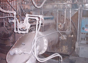
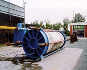
To integrate the pump/turbine into the process cost-effectively, Leigh decided not to attach a generator to it. However, because the existing DCAC circulating pumps use 200-hp induction motors, during the installation of the pump/turbine the motor of one of the two circ pumps was removed and replaced with a double-shaft extension motor. The pump/turbine (Figure 1) then was connected to the rear shaft of the motor. This arrangement uses the turbine to partially unload the motor.

1. Reverse operation. Running a pump in reverse (as a hydraulic turbine) recovered almost 100 brake horsepower at Air Products and Chemicals Inc.’s air separation plant in Baytown, Texas.Courtesy: Goulds Pumps
Following the installation, an initial performance test of the pump/turbine indicated that it was recovering 93.5 bhp at a pressure drop of 52 psi. The former figure was determined by measuring the motor current without the turbine and then again with the turbine installed, taking into account the differences in the motor’s efficiency and power factor at the two loads. Leigh and Sabini believe the increased performance may be due to the expansion of entrained air as it passes through the turbine. Although the circulating pump motor still has to supply some power, because the turbine now is unloading it, the motor draws less current. As a result, Air Products ends up with a power savings. Assuming a cost of electricity of about 4 cents/kWh, Air Products estimates that its annual energy bill is now about $24,000 lower than before the installation. Originally, based on the predicted energy recovery of 85 bhp, the payback time for the project was estimated at 2.4 years. However, at 93.5 bhp of actual recovery, payback is now expected in 2.1 years.
Staying above "stall speed"
Because the Air Products facility operates 24/7, the air separation process could not be shut down during installation, and that constraint complicated the piping scheme for the new pump/turbine. Any flow restriction across the line would reduce the pressure drop available (estimated at 55 psi) for the turbine. At its operating point on the performance curve the turbine can handle about 3,700 gpm, which would necessitate passing several hundred gpm through a bypass valve.
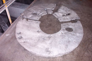
"If you decrease the pressure drop across the turbine too much, you reach a point at which no power at all comes from it," explains Leigh. "Due to the shape of the flow/head curve, if we were to reduce the pressure drop down to about 42 psi, you would have about 1,800 gpm flowing through the turbine, and we would get zero power." Even after reducing the diameter of the pipe feeding the turbine inlet nozzle from 18 inches to 8 inches, it was found that using standard concentric reducers would create a pressure drop that was too large. To solve the problem, Air Products and Goulds engineers fabricated a reducer with a long, tapered section to minimize the pressure loss across it (Figure 2). Once the reducer was installed, a greater pressure drop was available to produce power in the turbine.

2. Pressure reduction. A reducer with a long, tapered section minimized the pressure drop through it, increasing the pressure drop available for producing power in the pump/turbine.Courtesy: Goulds Pumps
—Courtesy of Goulds Pumps
ENERGY CONSERVATION
Insulation and lagging fundamentals
Power plant insulation and lagging should be three things: thermally efficient, cost-effective, and installed correctly. It is estimated that over the next five years the industry will spend more than $30 million to repair or replace improperly installed or designed insulation and lagging on new selective catalytic reduction (SCR) systems, boilers, and wind boxes. Leaky insulation and lagging waste energy, and—as any plant operator knows all too well—energy in any form isn’t cheap.
Keeping (relatively) cool
The average maximum temperatures within a steam power plant (in boiler flue gas and in air ducts to wind boxes, and on boiler walls) are typically between 500 and 700F. If you choose your insulation solely on the basis of its k-value (thermal conductivity), you may not be getting as much bang for the buck as you think. Why? Because almost all commonly chosen types of insulation have about the same k-value at the mean (rather than the maximum) operating temperature at which the rating applies. It’s interesting to note that insulation k-values have not improved significantly at all in the past 30 years.
Since the k-values of insulation are about the same, it’s important to examine the differences in insulation materials themselves, because the choice of material can have a big impact on the insulation’s durability, safety, and installation costs. The table compares the pros and cons of the four most common types of materials used to insulate power plant boilers, wind boxes, flues, ducts, and air pollution control equipment.

The pros and cons of four common power plant insulating materials. Source: Gary Bases
Big cover-up
Lagging is the finishing material (steel or aluminum) used to cover many types of insulation, especially those used on the many large flat surfaces within a power plant. Also known as cladding, lagging—without a vapor barrier—ranges in thickness from 0.032 to 0.063 inches (for aluminum) and from 20 gauge to 16 gauge (for steel). Generally, the installation of lagging is a custom job tailored to the equipment configuration (Figures 3 through 6).
3. Hot to trot. Typical burner front before insulation is applied.Courtesy: Gary Bases
4. Access required. Removable ceramic fiber blankets for burner fronts being fabricated.Courtesy: Gary Bases
5. Boarded up. Burner front with Class 4 mineral wool boards installed. Courtesy: Gary Bases
6. Ready for fire. Complete insulation job on a typical burner front.
Courtesy: Gary Bases
What does lagging do? First and foremost, it protects the insulation it covers by adding a flat and even surface layer. Lagging must be stiffened and fastened on adequate centers to prevent excessive deflection or "oil canning" when hot or cold.
The second purpose of lagging is weatherproofing. Properly installed flashings, slopes, and seals ensure total water run-off and prevent ponding or accumulation of water. Lest you think that lagging is only needed outdoors, remember that power plants regularly water-wash their indoor boilers and equipment. Water is the enemy of any insulation system, regardless of its location.
Handling expansion and contraction
Thermal expansion and contraction pose major problems for lagging installed on boilers, SCR systems, wind boxes, flues, or ducts between boilers and air heaters. As mentioned, these units and locations normally experience temperatures between 500 and 700F. Accordingly, the design of the lagging must take thermal expansion and contraction into account.
The forces of expansion and contraction can be shared and absorbed by some combination of the following:
- The lagging support system.
- The ribs of box-rib type lagging. (The ribs, or corrugations, allow the lagging to move with the contraction and expansion of the surface being covered.)
- The standing seam between flat lagging sheets.
- The flashing.
Energy savings mount
The design of insulation and lagging systems can have a big impact on the amount of energy used and lost at any steam power plant. The systems’ energy efficiency is directly proportional to the amount of fuel being used. For example, decreasing the surface temperature of a boiler by 10 degrees (say, from 140F to 130F) would save about 8 Btu/hr/ft2. Based on projected energy savings of $10 per million Btu of heat loss, insulating a boiler with a surface area of 100,000 square feet would save almost $3,000 a year.
—Contributed by Gary Bases, author of The Bril Book (a complete guide to brick, refractory, insulation, and lagging systems) and president of BRIL Inc., a consultancy specializing in energy-saving solutions. He can be reached at 330-665-2931 or [email protected].
MECHANICAL
A new way to repair concrete pipes
The worst nightmare of any owner of utility infrastructure is an unplanned, lengthy shutdown caused by the failure of a piece of equipment without a backup. The concrete pipes used by power plant cooling towers and water supply systems are a good example of an unprotected asset. Such pipelines not only lack redundancy, but—because they are underground—damage to them also is invisible and thus is usually not repaired until after the pipes fail. By taking the time to perform a condition assessment, you can prevent a pipeline from bursting and ensure that your business does not lose millions of dollars in revenue.
Most large water pipes are made of both concrete and reinforced steel. The combination is designed to resist both the internal forces created by water pressure and the external forces of soil weight and potential vehicle loads.
Within the pipes, a thin-gauge-steel cylinder serves as the core component for keeping them watertight. During manufacturing, the inside of the cylinder is lined with 2 inches of spray/shotcrete or concrete, which serves as a wearing surface. Concrete up to 8 inches thick is also sprayed on the outside of the cylinder, completing the pipe "core."
Still not enough
Strong as it seems, this core still is not capable of resisting external forces and internal water pressures of 125 psi and higher. To counteract these forces, a precompression force is applied to the core by tightly wrapping small, high-tensile steel wire around it. Another sprayed-on layer of concrete is then applied on top of this prestress wire wrapping for protection and durability purposes (Figure 7). Finally, Bell and spigot-type connections and rubber gaskets at the ends of the pipe are used to make rigid and watertight connections between sections.

7. Stressed out. Cross section of a typical prestress concrete pressure pipe. Over time, corrosion of the prestress wires can cause catastrophic pipe failure.
Courtesy: Structural Preservations Systems
Concrete pipes of this design have served power plants and water-supply systems successfully for the past 40 years. However, recently, there has been a spate of premature piping system failures in public and industrial settings. The cause of the failures seems to be directly or indirectly related to corrosion of the pipe’s critical structural element—the prestress steel wire wrapping. After the prestress wires corrode sufficiently, they either become loose or break.
At this point, the core steel cylinder is the only tensile element left to resist the pressures. But because the cylinder can withstand only 70 psi, when service or surge pressures in the system exceed this level, catastrophic failure is the inevitable result. Such failures in municipal aqueduct systems have released up to 20 million gallons of water (Figure 8). The failure of a cooling water pipe serving a power plant can be equally devastating if it shuts down the plant for days or longer and results in the loss of millions of dollars in revenues—and a huge repair bill as well.
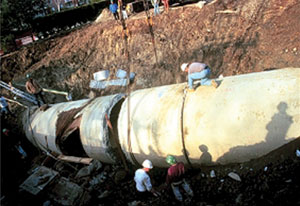
8. Bursting at the seams. Catastrophic failure of a 102-in.-diameter prestress concrete pipe due to prestress wire corrosion.
Courtesy: Structural Preservation Systems
Out of sight, out of mind
Although the pipes serving power plants are made of precast concrete, their durability is no match for age and constant exposure to water. It should come as no surprise that many of these pipes, which are between 20 and 40 years old and have never been inspected, are in poor condition and are on the verge of failure.
One of today’s state-of-the-art technologies rolls eddy current-based testing equipment through the pipe to locate breaks in the prestress wire. Breaks cause changes in the electromagnetic field within the pipe that sensitive instruments can detect, quantify, and pinpoint. Also available today are acoustic technologies that can locate wire breaks during normal operation.
A better mousetrap
The operators of power plants and water systems no longer need to either resign themselves to pipe failures or be more vigilant about testing—both of which result in expensive repairs. A new technique that has proven itself in industries other than utilities promises faster, less-disruptive, and more cost-effective repairs. It requires lining the inside of water pipes with a carbon fiber–reinforced polymer (CFRP) sheet.
CFRP sheets are paper-thin fabrics that can be bonded to concrete members (such as beam slabs or columns) with epoxy to significantly increase concrete’s load-bearing capacity. Such sheets, which have been used extensively in the aerospace, automotive, and sporting goods industries, are now becoming a mainstream technology for upgrading concrete structures.
Important characteristics of CFRPs for structural repair and strengthening applications include their corrosion resistance, speed and ease of installation, lower cost, and aesthetic appeal. As with any other externally bonded system, the bond between the CFRP system and the existing concrete is critical, as is surface preparation. Typically, installation entails applying an epoxy to the prepared surface, placing the CFRP fabric into the epoxy, and then applying a second layer of epoxy. After it cures, the CFRP composite laminate adds considerable structural capacity to the element despite its thinness, because the CFRP’s tensile strength is about 10 times that of steel.
CFRP technology recently proved itself in the water pipeline industry. Using it, the Providence Water Supply Board was able to repair rather than replace 50-year-old prestress concrete pipes in its aqueduct system when a major section of a 102-inch-diameter water line in Cranston, R.I., suffered a catastrophic failure. The water line ruptured when corroded prestress wires within it were no longer able to withstand 120 psi water pressure as well as excessive external loads.
Following the failure, testing identified other sections where prestress wire wrapping corrosion could be occurring. Inspections revealed vulnerabilities in 20 nonconsecutive 16-foot-long sections within a 5-mile stretch. Once Providence Water realized that strengthening these sections was vitally important to the long-term viability of the system, it retained Structural Preservation Systems Inc. (SPS)—a 30-year-old concrete repair contractor based in Hanover, Md.—to repair and strengthen the 20 suspect sections.
Testing the design
For the Providence Aqueduct, SPS’s design of the CFRP sheet lining assumed that the system’s existing prestressing wire could no longer handle both 125-psi service loads and the live and dead loads of the soil. Once the design was finalized, and before installation, SPS conducted full-scale testing on three pipe sections to validate its effectiveness (Figure 9).
9. Proof of concept tested. Full-scale testing on three pipe sections validated the effectiveness of the design. Testing multiple sections provided the opportunity to test a complete waterstop termination detail at both the spigot and bell ends of a pipe section.
Courtesy: Structural Preservation Systems
Before the lining was installed, pull tests were conducted to verify the strength of the bond between the CFRP and the concrete pipe surface. These tests revealed that all failures occurred in the concrete subsurface at an average of 300 psi—well over the 200 psi called for by the carbon fiber application guidelines.
Once the tests were complete, high-pressure water blasting removed sediment from the pipe’s interior to prepare the surface for application of the carbon fiber. Scaffolding was erected to allow technicians to reach the top of the pipe and to prevent walking on the bottom of the invert. To prepare the surface, an epoxy primer and then an epoxy putty material were applied to fill voids and level imperfections. The surfaces were now ready for the CFRP installation.
Prior to installation, the CFRP sheets were cut to a predetermined length in an above-ground staging area. Once the sheets were lowered into the work area, they were saturated with epoxy and then applied to the pipe’s circumference. Metal rib rollers were used to push out any air bubbles and to press the CFRP sheets into the epoxy saturant. A second layer of the saturant was then applied to form a complete fiber/laminate matrix. This process was repeated for subsequent layers of carbon fiber. Layers were internally wrapped both around the circumference of the pipe and longitudinally—essentially creating a "pipe within a pipe."
After the CFRP liner was installed, the prestressing strands of the center-strengthened section were cut to guarantee a full test of the CFRP. The pipe assembly was sealed with large steel bulkheads and then filled with water. Next, the test pipe was pressurized at increasing levels until it failed—at almost 300 psi, which is 2.5 times the service and surge pressures, and within 5% of the capacity of a new prestress concrete pressure pipe.
—Contributed by Jay Thomas, VP of Structural Preservation Systems Inc. (www.structural.net). He can be reached at 410-850-7000 or [email protected].