Focus on O&M (October 2006)
INSTRUMENTATION & CONTROLS
Upgrading to digital–twice
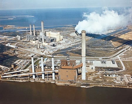
The E.W. Brown Generating Station of Kentucky Utilities (KU) is located in the town of Burgin, about 30 miles southwest of Lexington. The plant’s three generating units burn an average of 1.5 million tons of coal annually, delivering some 750 MW of power (Figure 1). By 2005, the control technology that had been installed 35 years prior was beginning to show its age and replacement parts were becoming harder to find. KU’s management concluded that the long-term benefits of replacing E.W. Brown’s aging control systems warranted the investment. The goal became keeping the cost as low as possible.

1. Time for a change. All three units of Kentucky Utilities’ E.W. Brown Generating Station need to have their controls systems upgraded. Some systems are three decades old, and replacement parts have become scarce. Shown is Unit 7. Courtesy: Invensys Process Systems
"We figured we had five years to upgrade three systems," said Jeff Fraley, plant manager. "Because of budget constraints, evaluated cost was a major criterion in our vendor selection process. Another was the supplier’s ability to evaluate our control strategy and help us achieve optimal performance in both the short and long terms."
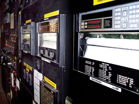
Most of the controls were so old that they required total replacement, from field device wiring and terminations through the controls. However, the field wiring, terminations, and cabinets of the data acquisition controls serving one of the Brown plant’s three units—Unit 7—were still intact (Figure 2).

2. Feeling its age. After 35 years of loyal service, the old control room was ready for a facelift. Courtesy: Invensys Process Systems
Of the controls vendors from which KU invited bids, only the Foxboro unit of Invensys Process Systems said it could deliver a modern digital control system that would preserve Unit 7’s existing infrastructure. Doing so would not only save the considerable cost of rewiring, but it also would reduce costly downtime by enabling the change from old to new controls to happen in hours, instead of the weeks estimated by competitors.
"We were able to switch from our legacy 1,334-point Westinghouse WDPF distributed control system [DCS] to a new I/A Series system over a weekend," said Greg Wilson, KU Brown project manager. "What’s more, the job was so easy that we did it ourselves."
Carpe diem
Because the I/A Series I/O modules plug easily into existing cabinets and racks, there was no need to move process wires or enlarge the system’s footprint. All that had to be added at the Brown plant were controllers and workstations (Figure 3).
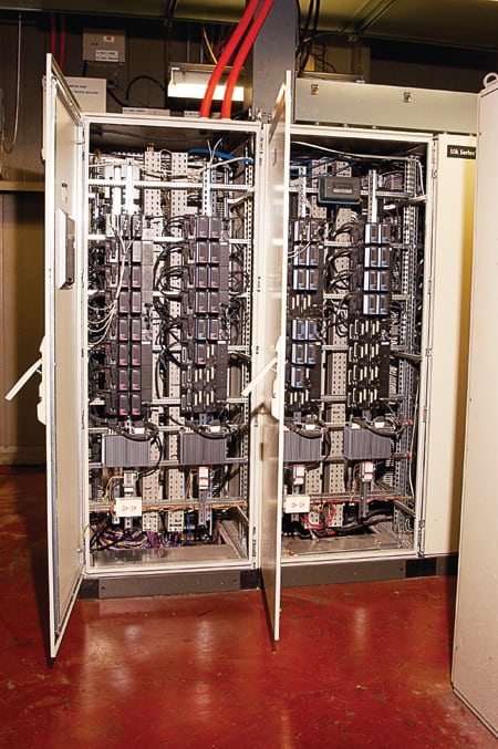
3. Fits like a glove. I/O module replacements fit into existing cabinets and racks, saving the existing wiring and installation time. Courtesy: Invensys Process Systems
To minimize service disruption during the switchover, the plan was for Foxboro engineers to assist with the installation during a scheduled shutdown. But when an unexpected tube leak forced an earlier shutdown of two days, KU engineers and technicians seized the opportunity and completed the entire installation over a weekend using their own maintenance technicians.
The techs handled the cutover flawlessly, plugging in the cards rack by rack and then testing all of the racks individually.
Having fully upgraded the data acquisition system (DAS) controls, the team then made good use of the later, scheduled outage. They reautomated Unit 7’s boiler, feed pumps, motor controls, and balance of plant using I/A Series technology and even extended the system to the turbine to optimize its performance and that of the overall unit. That required the addition of new Foxboro Fieldbus I/O modules, controllers, and workstations, which were integrated seamlessly with the plug-in Foxboro replacement of the legacy Westinghouse WDPF system.
Play it again, Sam
As KU realized that it had spent only a fraction of the industry’s going rate for a DAS upgrade and boiler reautomation, it was eager to replicate the project on the other two units of the Brown plant to reap similar performance improvements. As preparations for that work were advancing smoothly in 2005, an unexpected interruption stopped the project in its tracks.
In an event totally unrelated to the new controls, a 4-kV auxiliary switchgear failed and started a fire that destroyed all of the new DAS controls on Unit 7. All of the legacy fixtures, some of the new boiler controls, and a legacy annunciator system connected to the I/A Series controller were lost.
With the objective of returning quickly to service, Invensys sent in a team of Foxboro engineers to work with the KU maintenance team to complete what, this time, was a total control system migration. It included replacement of the DAS I/O cabinets, two I/A Series processor cabinets, all workstations and furniture, terminal assemblies, and smoke-damaged relays and power supplies.
Because the terminations and wiring had been destroyed, the new system required more reengineering than the initial project, as well as a full reinstall and checkout for a new generation of application workstations.
The recent experience installing I/A Series technology did, however, prove beneficial. For example, it made it much easier to replace the legacy alarm annunciator with a new Foxboro window alarm scanner program called WASP. All the points necessary for alarm annunciation were already available from easily configurable software tags supporting the DAS within the I/A Series system. The serial connections of the new fiberoptic communications system minimized the rewiring needed to hook up five new, 42-inch display panels.
Within five weeks of the fire, Invensys had engineered, tested, and shipped a replacement DCS. Seven weeks after that, the E.W. Brown plant was back up and running, with more functionality and capacity than it had prior to the fire. It’s worth noting that the Foxboro controls never caused any trips either during their commissioning or normal day-to-day operation (Figure 4).
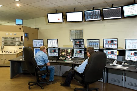
4. Required upgrade. Seven weeks after a fire destroyed the distributed control system, the new control room was up and running. Courtesy: Invensys Process Systems
Modernity mandate
Kentucky Utilities now is more confident than ever that upgrading the controls of the other two generating units at the Brown plant makes sense. Under full digital control, the boiler, turbine, and mechanical equipment of all three units will be more likely to deliver many more years of reliable service.
"Keeping our automation system up to date is no longer a luxury," said Brown Station Maintenance Manager Brian Sumner, "and the days of being locked into a multimillion-dollar control system that must be replaced every 10 or 15 years are over. The I/A Series system provides us an open, flexible digital control platform that can add the exact level of automation that is right for our business, as we need it."
—Contributed by Invensys Process Systems (www.foxboro.com).
Lower-cost turbine monitoring
Consumers Energy’s J.C. Weadock station in Essexville, Mich. (Figure 5), recently upgraded the supervisory instrumentation of the 155-MW Westinghouse steam turbine-generator powering Unit 7. Because the unit lacks a DCS, Project Manager Ed Denzer initially planned to purchase vibration instrumentation and a separate turbine monitoring system to replace old analog recorders and annunciators.
5. Who’s in charge? Turbine supervisory instrumentation was modernized at Consumers Energy’s J.C. Weadock station in Michigan. Courtesy: Consumers Energy
Then Denzer talked with Mid America Dynamics (www.madynamics.com), a controls integration specialist, which advised him that Rockwell Automation could integrate vibration as well as process data—represented by 100 resistance-temperature detectors and thermocouples and fifty 4- to 20-mA signals—into a single package. Taking the advice, Denzer ended up getting a system customized for Unit 7 that replaced the unit’s old chart and sequence-of-events (SOE) recorders and vibration monitoring systems. The new system (Figure 6) gives Weadock operators much of the monitoring functionality of a DCS at a much lower cost.
6. Panel-mounted. Unit 7’s old turbine supervisory instrumentation included high-maintenance analog alarm and trend recorders. Courtesy: Consumers Energy
The vibration monitoring system selected was the Allen-Bradley XM series from Rockwell Automation. Among its modules are eight x-y noncontact bearing sensors, two velocity probes, one for eccentricity, four for shell expansion, one for dual-channel differential expansion, two speed references and one phase reference, and two AC linear variable displacement transducers for monitoring valve position (Figure 7).
7. As good as a DCS. Upgrades included the installation of a client/server operator interface. Courtesy: Rockwell Automation
The XM condition monitoring and protection modules are integrated with Rockwell Automation’s Allen Bradley ControlLogix processor, VersaView operator interface system, and RSView human-machine interface software. Vibration data and standard supervisory control and data acquisition information can now be viewed and trended together to paint a clearer picture of Unit 7’s operations.
All of the data is available to Weadock operators through Rockwell Automation’s RSView client/server software. The system works as follows. VersaView panel-mounted computers, which were installed in the existing boiler and turbine control panels, graphically represent process conditions. Engineers can view the process data within RSView applications on their desktop PCs by connecting to the VersaView computers via the plant’s local-area network (LAN). All data in the RSView software are available for display, alarming, and trending on any VersaView operator terminal via touchscreen menus (Figure 8).

8. Touchy subject. A new touchscreen interface gives operators quick access to key operating parameters and trend lines. Courtesy: Consumers Energy
The heart of the system is Rockwell Automation’s ControlLogix control processor, which performs the control and monitoring functions. It is fed by Flex I/O modules that replaced chart recorders at eight locations across Unit 7. A remotely located ControlLogix I/O rack houses the SOE I/O modules that replaced SOE recorders, and a GPS module that serves as a master clock/time base accurate to within 100 microsecond. The system refreshes all screens every 500 ms and updates trend data in the database once a second. Because the SOE modules can handle 125 VDC inputs, it was possible to dispose of the relays needed to feed the old SOE recorder.
The two VersaView Servers oversee two VersaView clients configured as operator view stations and four other clients placed throughout the plant. The Modbus interfaces with Unit 7’s existing programmable logic controllers (PLCs) and uses the GPS time stamp to achieve a resolution of 100 microsecond.
A big benefit of the system is lower installation cost. Turbine-mounted sensors now are wired to a junction box mounted near the bearing, rather to the control panel via twisted pairs from each bearing. As a result, the power supplies for the XM module and all noncontact signal sensors can be mounted in that junction box as well. Depending on the distance from the turbine to the control panel, the saving on wiring installation can be anywhere from 40% to 60%.
The XM system is the next-best thing to a DCS, and a lot less expensive. It tells operators what they need to know, especially during turbine start-up and shutdown. The ControlLogix system supports the XM system by converting boiler pressure and temperature readings to optimal turbine ramp rates and turbine soak times (Figure 9).
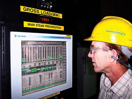
9. Invisible hand. Tim Histed, instrument & controls supervisor, checks the ControlLogix system that feeds vital information (such as turbine startup ramp rate and soak time) to operators of the J.C. Weadock station. Courtesy: Consumers Energy
—Contributed by Consumers Energy’s J.C. Weadock Station (www.consumersenergy.com) and Rockwell Automation (www.rockwellautomation.com).
Pros and cons of remote process control
Industrial automation is no longer confined by the walls of a production facility. More and more processes can be controlled remotely from an office or a home—or even from Starbucks. Today’s programmable logic controllers (PLCs) are so integrated with control systems that it is possible to monitor a web site or the vital statistics of an operating machine from any location with Internet access.
Making the PLC connection
The Ethernet port on new PLCs can be used for two purposes. The first is to control remote I/O on Ethernet-based protocols like EtherNet/IP, Profinet, or Modbus/TCP (UDP), to name a few. The second is to program and/or debug the controller’s firmware. By using the port and a web or file transfer protocol (FTP) server, it is possible to remotely administer any control process running at a power plant.
The first step in connecting remotely is to set up the controller to both interface with the plant’s LAN and to handle messages from a wide-area network (WAN) such as the Internet. This is accomplished by adding a gateway address to the controller’s Ethernet communication settings. Doing so enables the controller to send and receive IP messages beyond the local network.
The gateway address is usually assigned to an Ethernet router set up to direct IP traffic to the correct Ethernet device on the LAN. Routers come in all shapes and sizes, ranging from a computer with two network interface cards and routing software to an off-the-shelf broadband system. But they all handle traffic in pretty much the same way. The most common technique for routing network traffic between a LAN and a WAN is to use network address translation (NAT). NAT provides a means for multiple devices to share an Internet connection identified by a single IP address supplied by an Internet service provider.
Unfortunately, the NAT does not provide a true end-to-end connection. A TCP/IP connection established outside the local network may not be able to connect with the destination device because the IP address of the destination device is hidden behind the router. A technique called port forwarding must be used to make the connection. In port forwarding, communication from outside the network sends a message to the router’s IP address, and the router determines where to send the packet based on the port number. NAT’s lack of end-to-end connectivity may be considered a problem in some circumstances, but it also provides a simple means of network protection.
Cybersecurity options
Attaching a PLC on a plant control network to a network with Internet access exposes the machine to the same range of security threats to which unprotected computers are vulnerable. One of the best security measures—called "Security by Obscurity"—is to select a controller whose embedded operating system isn’t very familiar to hackers.
Another security option is to configure the router to protect the control network from potential attacks. NAT’s lack of end-to-end connectivity prevents most unsolicited requests for communication originating from beyond the LAN. When setting up a router, be sure to limit the number of open ports. For example, a miscreant could use an open FTP port to upload a virus or a program to override the operation of the controller. A good rule of thumb is to avoid keeping open any port that isn’t used regularly.
For increased security, a virtual private network (VPN) can be set up to encrypt any data traveling over a public network such as the Internet. Instead of opening all the ports that are needed to handle communication to the control network, one single authenticated network port passes the encrypted communication. This gives the user the same level of access as if he were on the LAN.
—Contributed by Paul Reszka, application engineer for Wago Corp. (www.wago.us), a specialist manufacturer of electrical and electronic components using spring-pressure termination technology. Reszka can be reached at 262-255-6333 ext. 154 or [email protected].
PLANT MAINTENANCE
Nuts about Superbolt
Located between Lake Ontario and Lake Erie on the U.S./Canadian border, Niagara Falls is the site of the world’s first hydroelectric plant. It went live on November 16, 1896, and was built by Nikola Tesla and Westinghouse Electric Co. Since then, several other power plants have been built on both sides of the river.
One of those plants is the 2,400-MW Niagara Falls Power Project, which went on-line in 1961 as the world’s largest hydroelectric plant at the time. It diverts 375,000 gallons of water per second from the Niagara River through a tunnel underneath the City of Niagara Falls and into a 164-billion gallon forebay. When demand is low, 12 pump-generators move the water into a 1,900-acre holding pond. During the day, when demand is high, the turbines switch from pumping to generating, adding to the available output. Each unit has six 2-inch bolts in its large shaft couplings that are difficult to remove and replace using traditional methods.
"We used to use a big, heavy hydraulic wrench to stretch the bolts, but that was cumbersome," explained Richard Halas, senior engineer at the Niagara Falls Power Project. "Even worse, the wrench would often score the surface underneath the nuts and sometimes damage the threads of the bolts themselves. As strike three, we had no way of knowing how much torque to apply."
To address these problems, about four years ago Halas switched from standard nuts to multijackbolt tensioners (MJTs). An MJT (Figure 10), which can be used to retrofit existing nuts or bolts, is installed hand-tight against a hardened washer. Instead of turning the entire nut, though, an MJT uses a series of jackbolts threaded through the body of the tensioner. The jackbolts can be tightened by a garden-variety handheld torque wrench or air gun. For this particular job, Halas ordered the type of jackbolts with lock-wire holes in them (called Superbolts) as an extra precaution against loosening.

10. Tight fit. A nut-style multijackbolt tensioner can be tightened by a handheld torque wrench. Courtesy: Superbolt Inc.
"Our mechanics really enjoyed installing the Superbolts since it takes just one person with a small ratchet wrench," said Halas. "They’re very easy to install, very easy to disassemble and—because they use pure tension—there’s no chance of damaging the bolt threads."
Since Halas began using the MJTs on the 12 pump-generators, he’s thought about using them for maintenance of the plant’s much larger main generators as well. Current practice is to use a hydraulic wrench that is so large it takes two or more men and chain pawls to lift and operate it, and special tools to remove it. "It’s not just that it’s heavy and cumbersome," said Halas. "It’s also dangerous, because of the very high hydraulic pressures and hoses involved. Although we’ve have never had any accidents, our mechanics definitely prefer the Superbolt nut."
Tension by torque
You may remember from Shop class that the strength of a screw fastener increases with the square of its diameter. A 6-inch bolt can handle 36 times as much load as a 1-in. bolt at the same bolt stress. Unfortunately, however, the torque it takes to tighten such a fastener increases with the cube of its diameter. So a 6-inch bolt requires 216 times as much force to tighten as a 1-incher.
Who but Popeye has the forearms to apply such torque? According to Allan Steinbock, a VP of Superbolt Inc. (an MJT manufacturer based in Carnegie, Pa.), "A number of alternative methods were developed because it’s impossible to tighten large bolts by hand."
Those methods include sledgehammers, crane wrenches, hydraulic wrenches, and thermal tightening. However, these "traditional" methods present a host of potential problems, including worker safety, equipment damage, time consumption, inaccuracy, insufficient bolt load, and—in the case of hydraulic methods, as represented by the wrench used on the main generators at Niagara Falls—expensive tooling.
MJTs eliminate these bolting problems by providing a safe, fast, and easy alternative that makes use of simple hand tools (see table). Another plus of MJTs is that they can be used in cramped areas where there may not be enough room to turn a wrench. In many cases, using an MJT may even improve equipment reliability. By adding elasticity to the fastener portion of a bolted joint, they typically help improve fatigue life and reduce leakage problems on gasketed joints. MJTs can be custom-designed to fit any size application.
Torque comparison. Superbolt vs. hydraulic wrench. Source: Superbolt Inc.
Deciding whether to upgrade to MJTs requires evaluating several factors in tandem. Obviously, an MJT’s capital cost is higher than that of a standard nut-and-bolt combo. But it may be possible to justify that cost premium against the total savings from avoided equipment downtime, the cost of hydraulic wrenches, and the elimination of problems such as stripped bolts or frozen studs. Another advantage of MJTs is improved worker safety, which is literally invaluable.
—Contributed by Superbolt Inc. (www.superbolt.com).