Focus on O&M (July/August 2006)
NUCLEAR MAINTENANCE
Safer, "virtual" reactor walkdowns
In an industry where safety comes first, Atomic Energy of Canada Ltd. (AECL) has found a way to minimize a major concern of nuclear plant shutdowns: exposing inspection personnel to radiation. With the help of a laser-based device called the FARO Laser Scanner LS (Figure 1), AECL reduces the risk of radiation exposure by creating a highly realistic 3-D image of the actual reactor and using it to guide required shutdown inspections.
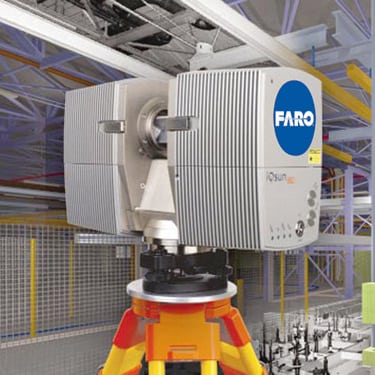
1. Virtual imaging. This laser scanner can produce realistic 3-D "blueprints" of in-accessible or hazardous locations—such as the interior of a nuclear reactor vault. Courtesy: FARO Technologies Inc.
The scanner recreates the interior of the reactor vault as a virtual environment, similar to a three-dimensional blueprint—everything is proportional and as detailed as a high-resolution photograph captured on silver-halide film (Figure 2). Using the scanner reduces from a dozen to one or two the number of engineers required to enter the reactor during shutdowns to measure and image components and structures. The fewer the participants, the lower the inspection team’s collective radiation exposure.
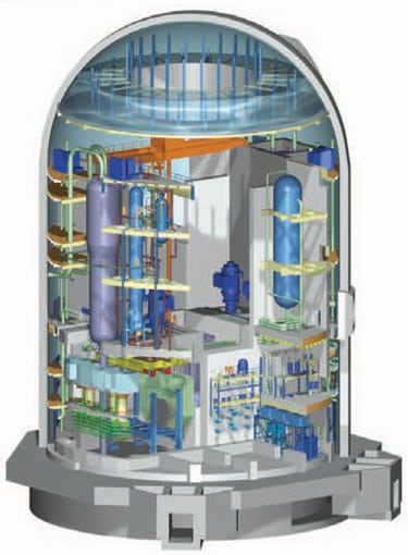
2. Keep a safe distance. Using a computer-generated image of the inside of a reactor reduces total worker radiation exposure. Courtesy: FARO Technologies Inc.
Based in Mississauga, Ontario, AECL plays a unique role in the global nuclear power industry by serving as a facilitator for plant operators worldwide. Established in 1952, AECL is the designer and builder of CANDU (CANada Deuterium Uranium) reactors, including the 700-MWe CANDU 6—one of the world’s top performers—and the new ACR-1000, a 1,200-MW-class unit. AECL’s more than 4,000 employees offer specialized technologies, R&D support, and cutting-edge nuclear services (design and engineering, construction and waste management, decommissioning) to all nuclear utilities, not just CANDU users.
Walkdown worries
The inside of a typical nuclear reactor is cavernous, up to 135 feet in diameter. The reactor core and support systems within it are equally impressive, comprising multiple tiers of equipment, catwalks, and platforms and a labyrinth of plumbing and control conduits. Once a year, reactors are shut down (and inspected with a fine-tooth comb), allowing the entire plant to be maintained. Shutdown procedures include machine alignment and balancing, refurbishment of blades and seals, the rewinding of motors and the replacement of bearings and valves, and—of course—comprehensive tests of all operational and safety systems.
Unlike a fossil-fueled power plant or an industrial plant, nuclear plants are built to specifications that are perhaps the tightest of any ever written. For instance, where a 7-inch gate valve is called for, not just any 7-inch gate valve will do; it must be the precise one called for in the plant specs, because that’s one that has proven to work. Substitute parts, or jury-rigged components that might suffice in another industry, are prohibited. This rigor is partially to prevent unexpected shutdowns, but primarily to prevent safety-related surprises.
During a so-called "walkdown" inspection of a reactor, engineers audit all the components, equipment, and key dimensions of its vault to verify that the reactor within it continues to meet as-designed specs and that no nonstandard components have been substituted for approved ones. Each valve, breaker box, motor, pump, doorway, and seal must be identified—and verified as correct—during the walkdown.
In the past, reactor walkdowns were labor-intensive tasks. Engineers in protective clothing had to clamber through the vault to measure critical dimensions such as the width of access doors and photograph everything needing positive identification. Although the engineers were trained to minimize their exposure to radiation, they wore badges or electronic dosimeters to monitor how much radiation they received during their time in the vault. Later, armed with their notes and a copy of the plant specifications, the engineers verified that all components and critical dimensions remained correct for the application.
Unfortunately, most physical walkdowns took so long that they put the health of the inspecting engineers at some risk.
Digital speed, film resolution
AECL discovered that the FARO Laser Scanner LS enabled a whole new paradigm for conducting walkdowns—one that limits radiation exposure for personnel.
Developed by FARO Technologies Inc. (Lake Mary, Fla.), the LS captures detailed images of big things. It has a range of 80 meters and can scan 360 degrees horizontally and 320 degrees vertically. Capturing 120,000 data points per second, a typical laser scan can be done in just 4.5 minutes—up to 100 times faster than most time-of-flight scans. The speed with which the LS scans is impressive, but its image resolution is even more so. After capturing a "data cloud" of about 28 million pixels per scan, the laser generates images in which minute details are razor-sharp, even at maximum range (Figure 3).
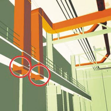
3. Industrial-strength scanner. High-resolution, photo-realistic images of large equipment can be produced in minutes. Courtesy: FARO Technologies Inc.
"Although the finished image is digital, it gives the same impression as a high-res photo," noted Mark Carney of the AECL Simulation Department, the companyÂ’s primary user of the Laser Scanner LS. One customer who scanned an entire business jet reports that details as fine as rivets and tire lugs are easily distinguishable on the scans. Others use the instrument to check the trueness of walls during tunnel construction, or to recreate the scene of vehicle accidents.
Because a typical reactor walkdown requires inspection of thousands of components, AECL personnel must scan the entire vault down to the smallest details. But a little planning and teamwork make each scan session go smoothly. Before a project begins, each engineering team responsible for checking a specific portion of the reactor gives Carney a shopping list of what it needs to see in its area of interest (Figure 4). "For example, one team will want to be sure that an access door is wide enough to move transfer flasks in and out; another will want to see the serial numbers on pumps," he said.
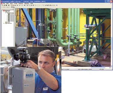
4. Small package, big results. The small, tripod-mounted laser scanner and high-resolution digital camera create crisp, full-color overlays. Courtesy: FARO Technologies Inc.
Carney and, occasionally, one other colleague travel to the reactor site and plan the specific positions from which they will do the line-of-sight scanning. They have two objectives. "Naturally, we make sure that we can cover everything important to the inspection. But we also have to make sure that the laser setups are compatible with the technology. For instance, we avoid locations where we would be scanning very shiny or deep black areas, because they are beyond the light range of the receiver."
Once the planning is done, the scanning team goes to work, setting up the scanner on its tripod, imaging all the equipment and vault surfaces that can be seen from that position, and then moving to the next area. Data from scans are saved in the instrument’s on-board computer. Carney and his cohorts have found that being thorough doesn’t necessarily take a lot of time because the scans go quickly. For instance, at one reactor in Canada, it took only four days to capture every area and item on the engineers’ shopping list. On some overseas jobs, it may take almost as long to fly to the site and back as it does to do the scanning.
Quilting bee
Once he has returned from a customer’s plant to his suburban Toronto office, Carney begins the process of assembling, in software, the individual scans into a single image of the entire reactor vault (Figure 5). "As we shoot each scene, we mark the edges of the area in the file, and those notations become the points at which we stitch all the areas together," he explained.

5. Stitch in time. Adjacent images can be automatically stitched together into a single, large image. Courtesy: FARO Technologies Inc.
When the stitching is complete, AECL has a virtual environment in which engineers can "move about" at will. They can change directions, examine particular areas from multiple perspectives, find the location of valves, read the serial numbers on junction boxes and other hardware, and check to see that no "creative engineering" has been added to the vault since the last inspection.
The usefulness of the virtual environment isn’t limited to visual inspections. Because the simulated vault is proportional in three dimensions, engineers can zoom in and measure dimensions of critical passageways or evaluate the flatness and plumbness of walls—as if they were inside the real vault.
Streamlined process
Before AECL made virtual nuclear inspections possible, reactor walkdowns required a dozen or more people to climb through a vault with tape measure, note pad, and digital camera in hand. Typically, it took thousands of person-hours in a "hot" environment to collect the required data.
Today, in-reactor time usually totals less than 100 hours per walkdown. The auditing portion of the project has been streamlined, too. Because the virtual environment is so much more accessible than the actual reactor, engineers can quickly verify that existing components and dimensions are those called for in the plant specifications.
—Contributed by FARO Technologies Inc. (www.faro.com or 800-736-0234).
GAS TURBINES
Beating the heat with inlet cooling
Gas turbine operators interested in boosting the capacity of their units should consider all turbine inlet cooling (TIC) technology options, including wet compression. According to the Turbine Inlet Cooling Association (www.turbineinletcooling.org), in wet compression "more fog is added to the inlet air than can be evaporated under the conditions of the ambient air. The air stream carries the excess fog into the compressor section of the combustion turbine (CT) where it further evaporates, cools the compressed air, and creates extra mass for boosting the CT output."
Seldom is wet compression evaluated head to head against other TIC technologies. Some consider that an unfair comparison, because in wet compression, some of the evaporation occurs in the turbine’s compressor section. However, because the wet compression system is installed ahead of the turbine inlet, it is indeed a TIC technology (Figure 6).
6. Wet and wild. Wet compression technology is installed before the turbine inlet. Source: Caldwell Energy
Evaporative cooling and wet compression use the latent heat from the vaporization of water to cool air in two places: ahead of the compressor inlet and within the compressor. The intracompressor cooling makes the unit work more efficiently, increasing its power output.
Wet compression has been retrofitted and proven on all types of CTs with no detrimental effects to the machine; most major turbine makers now offer the technology. When properly designed and implemented, wet compression produces power gains of more than 25%, independent of ambient conditions. The same benefit is realized on hot days and cold, however humid or dry. Additional benefits include reduced emissions and heat rate. Wet compression systems require about half as much water as a chiller’s cooling tower, even taking into account the latter’s condensate collection. Dry cooling towers are an option for chilling systems, but they degrade performance and require a much bigger footprint.
Economic drivers
TIC economics are often based on a design "hot" day, during which a CT’s output falls. However, because the exact temperature of the design day may never be experienced during any given summer, it should not be the sole basis of analysis. Turbine owners should evaluate not only the design day but also the site’s typical summer profile and ISO (International Standardization Organization) conditions. Most TIC providers will run an hourly economic analysis for a typical year.
Figure 7 illustrates published data for a three-turbine plant near Houston rated at 317 MW at 59F. The bars compare the impact on plant output of five TIC technologies on both hot days and ISO days. The hot day estimates are based on ambient dry-bulb and wet-bulb temperatures of 95F and 80F, respectively. As the data make clear, wet compression yields greater power gains than the other TIC technologies under both hot day and ISO day conditions; in the latter case, the capacity boost is substantial (from 317 MW to 365 MW, or 48 MW). Compared with wet compression, the gains achievable by chillers and fogging are much less.
7. Beat your heat. This chart shows net plant capacity vs. turbine inlet cooling technology under hot day (95F, 52% relative humidity) and ISO day conditions. Sources: Caldwell Energy Co. and Avalon Consulting Inc.
TIC technologies often are compared on the basis of their incremental capacity cost (ICC). This can be very misleading, because all of them—except wet compression—are ambient temperature–dependent. Each technology’s sensitivity to ambient conditions impacts its ICC at various combinations of temperature and humidity.
Figure 8 compares the ICC gains of the five TIC technologies. The electric chiller has an ICC of $395/kW on a design day but a much higher cost ($1,876/kW) on an ISO day. Because wet compression is not temperature-dependent, its ICCs on a hot day and an ISO day are nearly identical—$95 and $96 per kW.
8. The best option. Compare the incremental cost of capacity (ICC) gain vs. inlet cooling technology type under hot day and ISO day conditions. Sources: Caldwell Energy Co. and Avalon Consulting Inc.
Additive effects
Wet compression is unique in that its effects and ICCs are additive to those of other TIC technologies. Referring again to Figure 7, combining absorption chilling and wet compression would boost the 317-MW plant’s capacity by 9 MW (5 MW from the former and 4 MW from the latter) on a hot day and by 59 MW (11 MW plus 48 MW) on an ISO day. However, as Figure 8 shows, the maximum ICC gains would come from a system that combines wet compression with fogging—$128/kW and $150/kW, respectively, on the two days. The possibility of combining technologies should be considered as part of any analysis.
—Contributed by John E. Kraft, PE, president of Caldwell Energy Co. (Louisville, Ky., www.caldwellenergy.com).
ELECTRICAL
One-year payback for lightning protection system
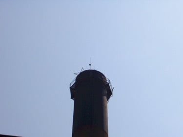
The 138-MW coal-fired Gadsden Electric Generating Plant in northeast Alabama (Figure 9) has supplied electricity to Alabama Power’s grid since 1949. Each of its two identical boilers generates 600,000 lb/hr of superheated steam at 875 psig and 900F. In 1995 a process steam line was added to supply a tire manufacturer nearly a mile away. To ensure 100% reliability of the saturated steam supply, at a flow of from 40,000 to 120,000 lb/hr, one of Gadsden’s boilers must remain on-line at all times. The process steam is sent through more than 5,000 feet of 12-in-diameter, above-ground, insulated steam pipe.
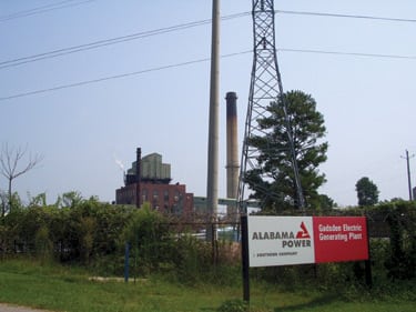
9. Spikes and surges. Gadsden Electric Generating Plant became susceptible to lightning after a process steam line nearly a mile long was added in 1995. Courtesy: Erico International Corp.
Problems arose shortly after the process steam line was put in. Electrical surges caused by lightning strikes increased in quantity and severity at the plant. Many were strong enough to shut down the steam host, cutting Gadsden’s output in half. Lightning-induced voltage spikes destroyed sensitive electronic equipment plantwide. Most of the lightning strikes occurred during the spring and fall, when the area is more prone to storms.
Gadsden became accustomed to paying $50,000 to $70,000 annually to repair "fried" equipment. The loss of process steam was even more costly to the tire manufacturer: a production loss of $80,000 to $100,000 per event.
New ground
Installation of an electrical protection system for Gadsden began in the fall of 2001 and was completed by mid-2002. The supplier was Erico International Corp. (Solon, Ohio), whose Six Point Protection Plan was designed to:
- Capture lightning strikes.
- Route their energy to ground.
- Dissipate it in the plant’s grounding system (which was upgraded).
- Bond all ground points together.
- Protect incoming AC power feeders.
- Protect low-voltage data/communication circuits.
This scope of work entailed adding lightning protection, surge suppression, and grounding. The lightning protection was provided by Eritech Dynaspheres. The Dynasphere—the protection system’s air terminal—is a spherical conductive dome surrounding an earthed lightning rod. The dome is insulated from the rod but connected to ground via a dynamically variable impedance with DC conduction. Dynaspheres were installed on Gadsden’s two tallest chimney structures (Figure 10), providing protection for more than 90% of the structures beneath them.
10. Top of the world. An Eritech Dynasphere (air terminal) was installed atop both of the plant’s two tallest structures. Courtesy: Erico International Corp.
Because the Dynaspheres weigh only about 6 pounds apiece, contractors were able to install both of them, at elevations of 151 and 300 feet, in less than two days without a large crane or specialized lifting and rigging equipment. That reduced the installation cost considerably.
Using standard grounding cable as downleader, the installers connected the air terminals to the plant’s ground electrode system and improved the grounding at the base of the stacks. The additional grounding consisted of ground rods and copper foil laid out in a crow’s foot pattern with Eritech ground enhancement material backfill. Together, the use of backfill and the placement of multiple ground rods at the termination of the downconductor lower the path’s impedance, increasing energy dissipation.
Simpler surge stoppage
The surge suppression called for in the system contract was provided by selected Erico Critec devices, which were to be installed on the cables of sensitive electronic gear. To minimize the devices required, a Gadsden engineer and the plant’s maintenance team leader began by reviewing the myriad cables, power supplies, and programmable logic control (PLC) networks at the plant. The two men determined that the most cost-effective approach would be to consolidate two power supplies: one for the plant’s main control system and the other for essential plant service.
This approach produced three big benefits:
- It allowed the 120-volt power system to be protected by a surge-protection device with a single service entrance.
- It protected not only the process steam system’s power supply but also the supply for the plant’s PLCs, computer work stations, package boiler controls, and security system.
- It reduced the cost of the project by reducing to 20 the number the number of surge-suppression devices required.
- Taking advantage of routine equipment outages, the surge-suppression devices were installed without interrupting steam service to the tire manufacturer. The Critec devices go by the nomenclatures SES, UTB, and TDX. The service entrance standard (SES) device (Figure 11) has dual UL-listed TVSS (transient voltage surge suppression)/secondary surge arresters, so it is usable on either the load or line side of a circuit. The universal transient barriers (UTB) devices feature a hybrid, three-stage clamping circuit to maximize equipment protection. The TDX units—based on Erico’s patented transient discriminating technology—were added wherever voltage regulation was poor.
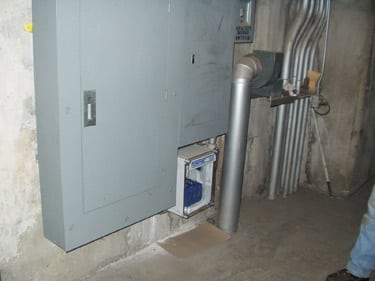
11. No-surge zone. The Critec SES device protects the electrical service entrance from surges and spikes. Courtesy: Erico International Corp.
Lightning-fast payback
The system installed at Gadsden all but eliminated electrical surges caused by lightning. Over the past three years, overall process steam reliability has improved to a near-perfect 99.8%. The only loss of steam supply to the tire maker occurred during the final weeks of the system’s installation. As a result, the project—which had a total installed cost of $87,000—paid for itself in less than one year.
—Contributed by Billy Zemo, a senior engineer at Gadsden. He can be reached at 256-543-5105.
WIRELESS COMMUNICATIONS
Reaching remote substations without fiber
Smaller distribution companies may feel they can’t afford to take off their training wheels and ride into the streets of wireless industrial automation. But shed the wheels of network cables and a distribution company (disco) can bring connectivity to remote infrastructure over a wide area without compromising data security or breaking the bank.
Just ask the Clinton Utilities Board (CUB), which serves 29,000 customers from the Tennessee town of the same name in the Cumberland Mountains. In 2002, CUB installed the first pieces of a supervisory control and data acquisition (Scada) system from Survalent Corp. (Mississauga, Ont.) on its lines, and then set up an Ethernet network (using fiber-optic cables and TCP/IP). CUB planned to expand the system’s hardware and software over time, eventually making it capable of remotely polling the remote terminal units of all of the disco’s substations.
Cumberland gap
Undaunted, CUB began investigating alternative telemetry methods: leased phone lines, licensed radio, unlicensed radio, even satellite. At the end of the day, the disco picked unlicensed radio as the most cost-effective, reliable, and secure option. The vendor chosen was ProSoft Technology Inc. (Bakersfield, Calif.), whose industrial-strength RadioLinx brand is known for its ability to intermix serial and Ethernet radios with embedded servers on the same network.
According to Todd Loggins of CUB, "The terrain made installing the wireless network quite a challenge. But the benefits it has produced made the effort well worth it. We’ve saved countless man-hours by being able to remotely monitor and control devices that normally would take us hours to get to."
Complicating the task at hand, each of the two substations lacked a line of sight to CUB’s main offices. ProSoft Technology’s tech support personnel helped develop a path study that concluded that if repeaters were placed on two mountaintop locations, both substations could be "seen."
One of the required repeaters was already in place; CUB had put it there to improve voice communications with company vehicles. The second location was then identified using GPS, but the top of that mountain was inaccessible to an ordinary vehicle. So CUB hired a local grading contractor to hump a 60-foot wood pole up the hill and plant it with the help of a bulldozer. ProSoft Technology then placed a solar-powered repeater kit and the necessary antennas on the pole, completing the new infrastructure part of the wireless project in December 2004.
At that point, ProSoft took over. The company installed RadioLinx Frequency Hopping Ethernet radios with serial servers at both substations. At the first, one radio monitors station loading from a Schlumberger Q1000 meter using the DNP 3.0 protocol. The meter has an RS-232 connection to the radio’s serial port and is directly polled from the Scada system’s master station using the radio’s port and IP address. To provide Ethernet connectivity, the old feeder breakers in this station were replaced with new VSA breakers and Form 6 recloser controls from Cooper Power Systems (Waukesha, Wis.). The new electronic controls are connected to the ProSoft radio through an additional Ethernet switch from RuggedCom Inc. (Woodbridge, Ont.). As a result, an RTU will never need to be installed at this substation.
The second substation has a Schlumberger Q1000 meter connected to the serial port of the radio, while a Cooper Form 6 control connects to the Ethernet port of the radio. Both are polled using DNP 3.0 over TCP/IP directly from the Scada master station. Plans call for upgrading the substation’s regulator controls to M2001C units from Beckwith Electric Co. Inc. (Largo, Fla.), which also have available Ethernet ports and use DNP 3.0. Although the upgrade will make an additional Ethernet switch or hub necessary, it will require only one radio—and no RTU.
Adding functionality
CUB recently began the second phase of its Scada system installation: enabling communications with pole-top devices (reclosers, regulator controls, automated switch controls, and capacitor controls) on distribution lines (Figure 12). ProSoft’s RadioLinx radios will be the primary communications vehicles. So far, the radios have been connected to Cooper Form 4C and Form 6 recloser controls and to Model 5801 automated switch controls from Chicago-based S&C Electric Co. The only protocol available for the Cooper Form 4C controls is Cooper 2179, which is not supported by the Scada master. The communications path to each of those controls starts at the "com" port on a substation RTU, goes through a serial radio to the same repeaters used for substation communications, and ends at the serial radio connected to the control.
1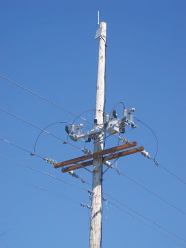
2. Off the beaten path. In Tennessee’s Cumberland Mountains, Clinton Utilities Board is four years into a project whose ultimate goal is to wirelessly interconnect its Scada system, 13 substations (two extremely remote ones), and thousands of pole-top devices. Courtesy: ProSoft Technology Inc.
Currently, Clinton Utilities Board has ProSoft 23 radios installed, and it hopes to double that number within the next six months. With such robust integration in its remote networks, any installed radio can then become a repeater for future radios.
—Contributed by ProSoft Technology Inc. (www.prosoft-technology.com)