Fire Safety in Modern Hydroelectric Stations
It may seem counterintuitive, but fire can be a serious danger in hydropower plants. In some respects, the danger is even greater than in thermal power stations. Most U.S. hydro plants are 30 to 70 years old but can deliver another 20 or 30 years of service with upgrades — including state-of-the-art fire protection systems. The design options outlined here also apply in large part to other generating stations.
Unlike fossil fuel – powered generating stations, hydroelectric projects consume a noncombustible "fuel" that also happens to be the most common and effective fire suppression agent — water (Figure 1). Our favorite fire suppression agent may be readily available in unlimited quantities, and often already under pressure, but don’t let that fact lull you into believing that hydroelectric stations are "fireproof."
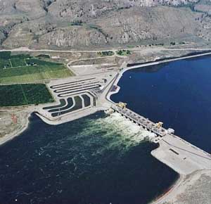
1. One of a kind. An aerial photo shows the Wells hydrocombine dam, owned and operated by PUD #1 of Douglas County, located on the Columbia River in the state of Washington.The first unit began commercial service in 1967. The generating units, spillways, switchyard, and fish passage facilities are combined in a single structure, or hydrocombine. Courtesy: PUD #1 of Douglas County, Wash.
It is true that hydro plants have perhaps the lowest fire risk among electric generating facilities, but that’s only because, generally speaking, the likelihood of a fire is lower than in a fossil-fueled power station. Hydro plants are not without fire risk, and history reminds us that large-loss fires have occurred (see table).
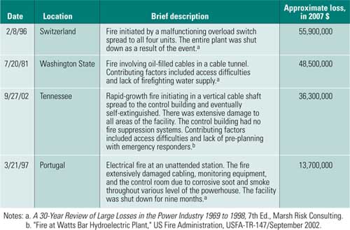
Sample of large-loss fires at hydroelectric generating facilities. Source:Starr Technical Risks Agency Inc.
Hydroelectric stations share many of the same fire hazards as their fossil-fueled cousins and, thus, share many of the same equipment and personnel policies. For example, common hazards include oil-filled transformers, electrical cables and switchgear, air-cooled generators, and large quantities of combustible hydraulic oil. Common fire hazards include hot work, smoking, general storage, and temporary construction/overhaul materials.
What differentiates hydro facilities from thermal power plants is that hydro plants are typically an underground/underwater windowless structure. In many ways, a hydro plant poses more extreme safety issues and rescue risks because of limited building access, lack of natural lighting, and embedded structures — all of which increase the potential of trapping workers on a lower level by a fire on a higher level.
The purpose of this article is to present the design basics of state-of-the-art fire protection systems for both life safety and equipment protection in a modernized hydroelectric facility. Many of the design approaches described also apply to other power generation facilities, so much of the discussion should be interesting to operators of a wide range of power plants. Many design options are clearly delineated in industry design standards, although several gray areas remain.
Life Safety Comes First
The number and type of life safety fire protection features at a facility — both active (such as fire alarms or fire suppression) and passive (including compartmentation or stairwells) — vary widely and normally depend on who designed the plant years ago and the design standards that were in place when the plant was originally constructed. However, the life safety design requirements for all structures share the same goal: Get the occupants out of the building in a safe and orderly fashion in case of emergency before conditions in the building become dangerous.
National Fire Protection Association (NFPA) 101 Life Safety Code (LSC) is the most comprehensive fire protection standard published and the foundation of egress and safety requirements in model building codes. The Occupational Safety and Health Administration generally recognizes compliance with the 2000 edition of the LSC and other applicable NFPA standards as sufficient to meet its General Duty Clause, which requires employers to "furnish to each of his employees employment and a place of employment which are free from recognized hazards that are causing or are likely to cause death or serious physical harm to his employees."
The LSC has a similar requirement applicable to the protection of fire hazards at hydroelectric facilities: "Every water-surrounded structure… shall have automatic, manual, or other protection that is appropriate to the particular hazard and that is designed to minimize danger to occupants in case of fire or other emergency."
Note that the LSC applies to both new and existing facilities, although the requirements for older, existing facilities are in some sections less restrictive. These two key code provisions guide much of the fire protection design or modernization of a hydroelectric powerhouse.
A life safety evaluation of a facility is a relatively complex project that requires one or more fire protection professionals with specialized knowledge, and this article isn’t a substitute for such expertise. However, there are several key design issues you should have knowledge of if you are involved in the refurbishment of a hydroelectric plant.
Exit and Maximum Distances. The LSC gives requirements on exit, maximum travel distance, maximum common path of travel, and maximum dead-end corridor distance. An exit is more than just a door out of the powerhouse; it’s also an entrance to a space within the building where occupants are supposed to be "safe" until they are able to leave the building. For most powerhouses, this is one or more suitably enclosed stair towers that lead occupants outside the building.
The maximum travel distance is the actual distance that a person must walk from the most remote portion of the plant to reach the exit. The LSC does assume that the occupant is in the same compartment as the fire and must get to an exit. This distance is not always a straight line. The common path is the portion of exit access that must be traversed before two separate and distinct exit path options become available: If one exit is blocked, an alternate choice of exits must be available while minimizing exposure to the fire.
A travel path dead end occurs in a corridor when that corridor continues past an exit, creating a pocket with no escape path except by retracing steps. Common paths and dead-end distances are always less than the maximum travel distance. For example, in a typical hydro powerhouse, the maximum travel distance is 300 feet, the common path is 50 feet, and a dead end is 50 feet.
Escape Stairs. Unless an exit can be accessed within the permitted common path distance, at least two means of egress must be provided from every plant level with at least one exit reachable without going through another level. The LSC permits fire escape ladders and alternating tread devices as means of egress. If the powerhouse has a level located more than 30 feet below the lowest level of exit discharge (that is, a safe location outside the building), or has more than one level located below the lowest level of exit discharge, exits must be of fire-rated construction.
Powerhouses, other than small ones with only one or two levels, generally require two enclosed stair towers with a two-hour fire rating. Grated steel stairs and landings are acceptable, but stair exits must have provisions to vent smoke, typically with a dedicated fan designed to produce a minimum pressure difference of 0.10 inch of water column and a maximum force of 30 pounds to open the doors, among other requirements.
Spaces not subject to human occupancy are exempt from egress capacity requirements. These spaces include scroll cases, generators, inspection access tunnels, draft tubes, and penstocks, according to NFPA 851.
Fire Doors. Fire doors leading to the stairwells must be kept closed at all times; using wedges or fusible links to hold the doors open is not permitted. However, the LSC permits the provision of automatic devices that allow the door to remain open but to close automatically in case of fire. If the entire powerhouse is provided with automatic smoke detection, then the electromagnets can be interlocked to automatically close the door(s) if smoke is detected in the powerhouse. As an alternative, consider using interlocking integral smoke detector/door closer assemblies. The LSC requires interlocking all automatic-closing doors in a stair enclosure so that the automatic actuation of one door closure device results in the closure of all automatic-closing doors.
Administrative Areas. Most powerhouses contain an administrative area that may be classified either as either an ancillary space or as business occupancy. As a rule of thumb, small offices used by operators or the shift supervisor, or as a break room, are considered to be ancillary and do not need to be classified as separate occupancy.
Conversely, a typical office setting with multiple offices, a reception area, and the presence of persons not intimately familiar with the hydroelectric facility (such as secretaries, accountants, and human resources staff) would qualify as separate business occupancy. In this case, the administrative portion of the powerhouse cannot exit into an industrial portion of the powerhouse. The office area must have its own exit arrangement, such as exit corridors and/or direct access to a stair tower.
Fire Alarms. The LSC requires the presence of a fire alarm system if the powerhouse occupancy is 100 or more persons and 25 or more of these occupants are above or below the level of exit discharge. In effect, just about all powerhouses will require a fire alarm system designed to meet NFPA 72. The proper design and installation of fire alarm systems is a separate topic that is outside the scope of this article.
Lighting. Emergency lighting in the event of power loss is required. The only exception is for powerhouses that are not "routinely inhabited," meaning unmanned powerhouses where operators only perform occasional checks and testing. Emergency lighting is not necessarily required throughout the powerhouse, but it is required in stairs, aisles, corridors, ramps, and passageways. Refer to NFPA 110, Standard for Emergency and Standby Power Systems, for specific requirements.
Some facilities require operators to carry a flashlight at all times. In one recent situation, a supervisor with a flashlight likely prevented multiple fatalities during a facility fire.
Equipment Protection
As previously mentioned, the LSC requires that fire hazards be properly protected. An additional benefit to the protection of hazards is protecting equipment to minimize a prolonged forced outage and expensive repairs.
The most relevant protection guideline and industry standard is the 2005 edition of NFPA 851, Recommended Practice for Hydroelectric Generating Stations. As its title implies, NFPA 851 defines good industry practices for safeguarding property and the continuity of power production and is applicable to both new and existing facilities. One proviso: The standard acknowledges that portions of it may not be justified for all facilities, particularly those under 25 MW. The standard relies on a "Fire Risk Evaluation" to determine separation, protection, and ignition sources control requirements on a site-specific basis.
The traditionally used fire extinguishing agent at most hydroelectric facilities is carbon dioxide (CO2) because of its nonconductive properties and lack of residue. As a result of recent fatalities involving CO2 fire extinguishing systems (see "Review of the Use of Carbon Dioxide Total Flooding Fire Extinguishing Systems," Wickham Associates, August 8, 2003) and a general trend toward personnel safety awareness in the industry, CO2 is falling out of favor in some quarters. There are no regulatory mandates at this time that preclude the use of CO2 as a fire-extinguishing agent (Figure 2); however, there are some relatively new personnel safety requirements.
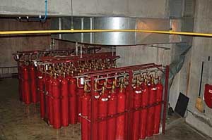
2. Got CO2? A bank of carbon dioxide cylinders stand ready to protect a hydroelectric generator. This arrangement includes an initial and extended discharge bank of cylinders plus a connected reserve bank of cylinders. Courtesy: PUD #1 of Douglas County, Wash.
CO2 is an excellent fire suppression agent, but it does have some significant shortcomings. Dangerous situations can occur if the proper safeguards described in NFPA 12, Carbon Dioxide Fire Extinguishing Systems, are not followed. The first drawback is that it displaces oxygen in a space and is thus lethal at concentrations necessary for flame extinguishment. In addition, the effectiveness of CO2 is highly dependent on the integrity of the protected enclosure, as leaks can dilute the concentration of CO2 to the point where it is no longer effective.
CO2 has traditionally been used in oil storage and treatment rooms in a questionable application where the use of automatic sprinkler protection is a more effective and less expensive option. Making decisions without a thorough understanding of the potential hazards of the environment and the extinguishment agent will only exacerbate problems. Contrary to popular belief, automatic sprinkler protection, water spray, and/or water mist systems are effective in protecting against oil fires and are thus suitable for oil hazards.
Another misapplication of fire protection is using fire detectors (smoke and/or heat detectors) as a substitute for automatic fire suppression systems. Detection systems only provide early notification; they don’t actively control or suppress fire. However, when the hazard and risk are not great enough to warrant installation of fixed suppression systems, automatic fire detection may provide an acceptable level of protection.
Generators. Hydroelectric generators have a rather unusual design, with relatively large open areas exposing miles of combustible winding insulation that can propagate a fire. There is an ample fire history involving these machines, especially generators with the older asphalt-based insulation materials. Current winding technology employs epoxy-fiberglass materials that have reduced the fire hazard (Figure 3).
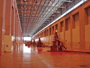
3. Generator hall. A typical hydroelectric generator deck with 11 hydroelectric turbinegenerators rated at 1,300 MW total at the Rocky Reach Hydro Project on the Columbia River, owned and operated by PUD #1 of Chelan County, Wash. The first seven generators entered commercial service in 1961. Courtesy: Dominique Dieken
CO2 fire suppression systems are traditional for generator windings, although an acceptable alternative is deluge water spray. The application of water to a generator may appear counterintuitive at first glance, but there are no known cases where a properly designed water spray system has caused any significant damage to a generator. NFPA 851 recommends an interlock to ensure the water spray system trips the generator off-line before releasing water. A common method of protecting against inadvertent water spray discharge into the generator is to interlock the water spray system with both heat detection and a generator fault. NFPA 851 also recommends that the generator should be electrically isolated and run without excitation for at least 24 hours after a water spray discharge.
Unfortunately, guidance for when to provide a fixed fire suppression system for the generator is less clear-cut. NFPA 851 states: "[p]rotection of generator windings consisting of materials that will not self-extinguish when de-energized should be provided." NFPA 851 further explains that "[t]hermoset [insulation] does not require fire suppression systems."
One global insurer, FM Global (formerly Factory Mutual), takes a somewhat different approach. The current FM Global standard, Data Sheet 5-3/13-2, Hydroelectric Power Plants, requires fire protection systems for generators rated at 50 MVA and over, regardless of winding composition. The May 2008 update of the standard states that "FM Global has a report of a generator fire showing fault energies were sufficient to ignite and result in a self-propagating fire in thermoset insulation." FM Global made a recent proposal to change to NFPA 851 based on this event. The next edition of NFPA 851, in 2010, may include some changes based on recent outcomes.
Transformers. The protection standards for outdoor oil-filled transformers holding more than 500 gallons are the same as those for conventional electric generating stations (Figure 4). In sum, all transformers must have secondary spill containment and either spatial separation distance between each other (25 feet up to 5,000 gallons and 50 feet for transformers with more than 5,000 gallons of oil) or firewalls.
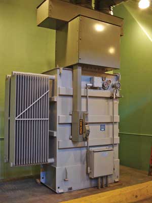
4. Managing voltage. This indoor oilfilled transformer uses fire-resistive dielectric fluid and proper spill containment. Courtesy:Dominique Dieken
Although not explicitly stated in NFPA 851, using water spray systems is typically acceptable as an alternative if spatial separation distance or firewalls are impractical. Water spray systems, if provided, are typically for the protection of exposed transformers or structures, rather than for the protection of the transformer itself (Figure 5). We find that adding water spray systems solely for the benefit of the transformer itself is not cost-justified for transformers less than 300 MVA if adequate separation distance or properly designed firewalls are provided.
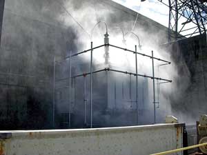
5. Ocean spray. The acceptance test of a new step-up transformer deluge water spray system
is under way. Note the firewalls on each side of transformer. Courtesy: PUD #1 of Chelan
County, Wash.
Oil-filled transformers located inside the powerhouse present a separate hazard, because a fire involving the dielectric fluid could severely expose the powerhouse and equipment to severe damage. Hazard mitigation includes replacing the mineral dielectric fluid with a listed/approved less-hazardous fluid, such as silicone or vegetable-based fluids. As an alternative, the transformer should be located in a fire-rated vault designed in accordance with the requirements of NFPA 70. Although this is not specifically required by the National Electric Code. the vault should be equipped with an automatic fire suppression system, such as CO2, water spray, or water mist.
Fire Protection Water Supplies. Hydroelectric facilities have an advantage over their fossil fuel – fired cousins by virtue of having an unlimited supply of water for fire protection at their fingertips. Medium- and high-head hydroelectric facilities have an added advantage: The water is already under sufficient pressure for fire protection use.
As a general rule of thumb, an available supply pressure of 50 psi or more is adequate for most fixed water-based fire suppression systems. However, NFPA 14 requires that a Class I automatic wet standpipe have a minimum pressure of 100 psi, so one or more fire pumps may still be required. The maximum allowable pressure in a fire protection system is 175 psi.
When using a penstock as a water supply source, two separate auxiliary connections dedicated to fire protection water should be provided upstream of any other valves (Figure 6). In addition, an auxiliary water supply — such as a connection to a gravity tank, a pressure tank, a municipal water source, or a pumping system taking suction from the tailrace — can also be a fire water source when the penstock is dewatered.
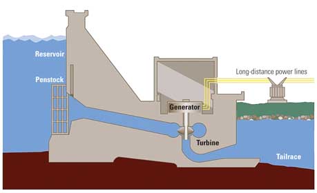
6. Water works. Pressurized water from the penstock can be used for fire protection if the head pressure is sufficient. The tailrace (the channel that carries water away from the dam) can also serve as a water source when the penstock is drained for maintenance. Source: Tennessee Valley Authority
In the case of a low-head hydroelectric facility (such as run-of-the-river plants) the pressure must come from dedicated fire pumps. The pump suction source should be a dedicated and reliable one, such as independent connections to at least two scroll cases, although NFPA 851 does not provide specific guidance on this.
Size the water supply to meet the flow demand of the largest fixed fire protection system(s) plus a minimum hose stream demand of 500 gpm for a minimum duration of two hours. Be aware that the largest system demand might require multiple suppression systems to operate simultaneously. A typical fire pump rating is 1,500 gpm at 100 psi if deluge water spray systems are present. Note that with the proper suction conditions, a fire pump can operate anywhere on its operating curve, up to 150% of its rated capacity; however, in accordance with good fire protection engineering practice, the maximum anticipated flow should lie between 90% and 120% of the rated capacity. New fire pumps are required to be located in a separate two-hour fire-rated room.
Neither NFPA 851, other NFPA standards, nor model fire codes require a redundant fire pump; rather, the design is driven by the desired system reliability. Normally, prudent fire protection design, not to mention most insurance companies, require a redundant fire pump. The common design practice is to provide two electric-driven pumps with redundant power supplies. Connecting each pump to a separate transformer via a separate breaker or to a single power supply with an emergency power source via a dedicated transfer switch meets this requirement (Figure 7).
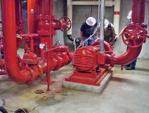
7. Double your flow. A typical fire pump system consists of redundant pumps located on a lower level of a powerhouse with completely separate power sources. Courtesy: PUD #1 of Chelan County, Wash.
Hydraulic and Lubricating Oil. The typical hydraulic governor contains several thousand gallons of oil at very high pressures. Hydraulic oil is commonly a mineral oil and a Class IIIB combustible liquid. Industry loss history finds that hydraulic oil – caused fires have not been significant, and the protection of such is not commonly found in the industry.
However, a leak can cause an atomized oil spray that can be ignited by an ordinary ignition source. We agree that the likelihood of such a fire is low, but the number of units in an open powerhouse multiplies the potential consequences of a hydraulic oil fire. Neither NFPA 851 nor FM DS 5-3/13-2 gives any concrete guidance for the protection of hydraulic oil systems. In my opinion, such fire protection is warranted in large open powerhouses with multiple units. If the protection is to be provided, automatic wet pipe sprinkler protection at the ceiling in combination with proper secondary spill containment represents an appropriate level of protection; the additional cost of deluge or preaction sprinkler systems is typically not warranted.
Most hydroelectric turbine-generators lubricate thrust and guide bearings from sumps that contain noncirculating mineral oil at atmospheric pressure. These types of lubrication systems do not generally pose a special fire hazard. Furthermore, you can reduce the likelihood of a fire with sound piping design, such as by avoiding threaded fittings.
Electrical Equipment. Multiple stacked cable trays and oil-filled cables pose the highest fire risk and have been involved in multiple high-profile fires in many power stations. Fire-resistant cable insulation does not preclude the need for fixed fire suppression systems. As a rule of thumb, use fire suppression systems when cable trays are stacked more than four high, as this arrangement appears to be optimum for propagating fires.
Wet pipe or preaction sprinkler systems offer a satisfactory level of protection, but use additional sidewall sprinklers pointed at a right angle to the trays if full penetration from above isn’t possible. Cables in metallic conduit typically do not require fire protection, so use automatic smoke detection in areas where cable concentrations do not warrant fire suppression systems.
Provide automatic smoke detection in relay, computer, telecommunications, and electrical rooms, as well as control rooms with low occupancy, because they are only a moderate fire risk. Control rooms may require fire detection and/or suppression systems behind walk-in control boards or beneath raised floors if a fire could go undetected for any length of time. Photoelectric smoke detectors respond better to electrical fires than ionization detectors.
NFPA 72 has specific requirements for the placement of smoke detectors along ceilings with obstructions, such as pockets formed by beams. Mount smoke detectors on the bottom of beams or at the ceiling if the beam depth is less than 10% of the ceiling height. Otherwise, detectors must be located at the ceiling in each pocket.
An important yet often overlooked area of fire protection is firestopping cable, conduit, and cable tray penetrations through floors, walls, and ceilings. The National Electrical Code requires that "[o]penings around electrical penetrations through fire-resistant-rated walls, partitions, floors, or ceilings shall be firestopped using approved methods to maintain the fire resistance rating." Firestopping seals penetrations with a special noncombustible sealant that swells when exposed to heat and prevents fire and smoke from spreading from one room to another.
There is an extensive fire history of poor firestopping, the most notable case being the Browns Ferry Nuclear Power Plant fire in 1975.
—Dominique Dieken, PE, CFPS (dominique.[email protected]) is a senior fire protection engineer for Starr Technical Risks Agency Inc., a member of the C.V. Starr & Co., Inc. group of companies.