Finding and fixing cracks in high-temperature headers
Major failures of superheater and reheater outlet headers are relatively infrequent. But when headers do fail, repairing them may take weeks, and replacing them may take up to six months. Forced outages are expensive, so it is imperative to develop and follow a routine inspection program for high-pressure/temperature steam headers. Early detection, monitoring, and repair performed on your schedule is always preferable to that phone call in the middle of the night.
Ideally, the inspection of a high-temperature header should begin with a magnetic particle examination of all of the welds on it—including circumferential butt welds, seam welds, header-to-tube stub welds, and any penetration and attachment welds. The inspection should be followed by a volumetric examination of any butt welds and a remote visual (borescopic) examination of the interior of the header, and then by in-situ metallographic examination (replication) and hardness testing.
If your plant is new or doesn’t have a history of steam header problems, or if your budget or outage schedule wouldn’t allow a comprehensive header inspection, consider a limited inspection. Restrict it to headers prone to service-related deterioration and to areas on them where a row of tube holes substantially overlaps or bisects a circumferential butt weld (Figure 1). Recent reports from the field indicate that these areas may be susceptible to severe ligament cracking. The level of susceptibility has three factors: the designs of the header and the weld, the composition of the weld’s final filler material, and the stresses associated with normal operation.
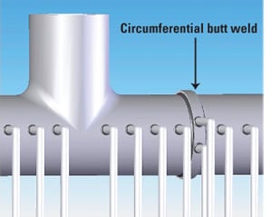
1. Ligament damage. Circumferential butt welds on high-temperature/pressure steam headers have proven susceptible to deterioration. They should be regularly inspected. Courtesy: Thielsch Engineering Inc.
Pay now, or pay later
In components such as superheater and reheater outlet headers, which incorporate multiple radial tube bores, the ligaments between adjacent tube bores endure the highest stresses of any header body part. The stresses are high because each tube hole effectively reduces the cross-sectional area of the header and thus its load-bearing capacity. High-temperature headers are made very thick to compensate for this reduction in cross-sectional area.
Because thicker headers cost more, some boiler makers have been known to supply headers whose wall thickness is at or barely above the minimum required by the applicable boiler code. Obviously, such headers are more susceptible to failure than those incorporating a safety margin. That is particularly true for headers that encounter stresses not anticipated by the designer. These include applied bending stresses caused by malfunctioning supports, thermal stresses produced by rushed start-ups, and the thermal stresses peculiar to the cycling of units that were not designed to be cycled.
Thin is not in
Typically, steam headers are fabricated from several sections of pipe and one or more fittings that are joined by circumferential butt welds. When welding pipes, some boiler makers counterbore their inside diameter surface, to prevent or reduce mismatches caused by out-of-round pipes and/or variations in pipe wall thickness. The counterboring makes it easier to fit-up circumferential butt welds, but at the cost of reducing the cross-sectional thickness of the header by about 1/4 inch to 3/8 inch. Thinner headers, of course, cannot bear as much load and are more vulnerable to mechanical fatigue.
The tradeoff may be even more costly if the boiler maker chooses to "flat-top" the circumferential girth welds. This practice, which appears to be an effort to preclude excessive reinforcement while improving the aesthetics of the surface, may remove too much material from the header, further reducing its joint strength and longevity.
Carbon cap causes problem
From the 1940s to the 1970s, certain manufacturers of electric utility boilers promoted the use of so-called Croloy welding electrodes. The stated value proposition for the Croloy electrodes was that because they had less chromium, molybdenum, and carbon than standard steel-alloy electrodes, they would not require as much preheating to be welded.
However, subsequent laboratory testing of the low-carbon, low-alloy electrodes revealed their creep strength in certain regions to be 20% to 30% lower than that of standard, chromium-molybdenum alloy steel electrodes. This made headers more susceptible to creep damage, particularly along their length.
On boiler tubes, the lower resistance to creep damage had only a minor effect on life expectancy. But for heavy wall components such as superheater and reheater outlet headers, the lower creep strength heavily influenced longevity.
The usual suspect
In recent years, thinness and creep damage—acting alone and in combination—have caused severe ligament cracking in a number of high-temperature steam headers. Often, the cracks, at the locations of circumferential butt welds, have been severe enough to require a unit shutdown.
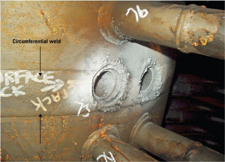
Two case studies provide anecdotal evidence that the cracking is attributable to poor welding practice. In one case, a visual inspection of a header at a Midwest utility steam plant revealed ligament cracking in multiple tube rows (Figure 2). The most severe cracks were in tube holes that overlapped circumferential girth welds—which a borescopic inspection (Figure 3) revealed were counterbored and flat-topped during the unit’s fabrication. A subsequent metallurgical evaluation confirmed that the girth welds, which had been completed using low-carbon filler material, were vulnerable to advanced creep deterioration. Surprisingly, the header base material itself showed no evidence of creep deterioration.
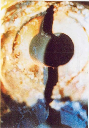
2. Crack attack. A circumferential crack that spanned the thickness of a high-temperature header. Courtesy: Thielsch Engineering Inc.

3. Trust your eyes. An example of the significant cracking along the inside diameter of the header, as revealed by a borescopic inspection. Courtesy: Thielsch Engineering Inc.
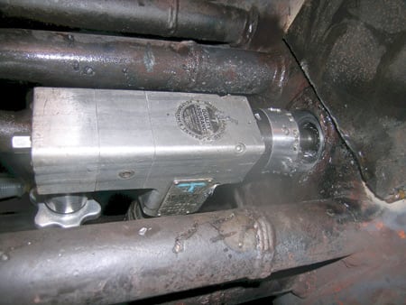
4. Bored to death. Bore holes after removal of tube stubs. Note the location of the circumferential weld. Courtesy: Thielsch Engineering Inc.
In the second case, a high-temperature header in a steam generator powering a plant in the Southeast began leaking after 28 years of service (Figure 4). Again, a visual inspection confirmed that, in the area where the leak occurred, the tube holes substantially overlapped a circumferential girth weld that was counterbored and used a low-carbon filler material. A borescopic inspection revealed ligament cracking across the cross-section of the header, which metallurgical testing confirmed was prone to cracking at points where it was welded to boiler tubes. No additional cracking was evident at any of the other 250 welds of the header-to-tube stubs.
Anatomy of a weld repair
The lessons learned from these two cases proved invaluable when a Midwestern utility hired Thielsch Engineering (www.thielsch.com) to propose how to handle a cracked reheat outlet header on one of its units. The utility wanted to know if the header, which had been in service for 28 years and had accumulated well over 200,000 hours of operation, could be weld-repaired. If not, it would have to be replaced, and that would require a lengthy and expensive shutdown of the unit.
After performing and evaluating nondestructive examination (NDE) reports on the header, Thielsch Engineering determined that the type of cracking observed could indeed be repaired by welding, but only if proper procedures were followed. Thielsch Engineering implemented a customized repair program encompassing several phases. The program began with NDE, followed by crack removal, preheating, welding, post-weld heat treatment, and final machining of the tube stub-to-header connections.
Air-arc gouging removed most of the crack. It was followed by grinding of the final groove, required for the weld repair. Ceramic heating pads of several electric resistance heaters were attached to the outside diameter surface of the header and then covered with insulation to properly preheat the header. The preheated area extended 24 inches in either direction and around the full circumference of the header. The preheat temperature was then raised 200 degrees F per hour to a temperature of 550F (Figure 5) before the ligament could be welded. Prior to welding, each area was carefully checked with Tempilstiks to ensure that the minimum preheat temperature had been achieved. The preheat temperature was monitored by thermocouples and Tempilstiks throughout the entire repair process. Finally, the area was heat-soaked at 500F for a minimum of three hours.

5. Hot to trot. The joint was preheated to 550F to begin the weld repair. Courtesy: Thielsch Engineering Inc.
Type and technique important
The weld repair used the shielded metal arc, or "stick" welding process. Electrodes ranging in diameter from 3/32 inch to 1/8 inch were used. Because the cracking within the original girth weld was likely related to the low-carbon electrode used during the header’s fabrication, AWS E9018-B3 electrodes were used rather than AWS E-9018-B3L electrodes. The former type is at most 0.15% carbon, making it a good match for the original base material used during the header fabrication.
Welding technique also played a key role in the repair. In this case, Thielsch technicians used a specially developed low-stress buttering technique. The buttering process involves laying stringer beads with 3/32-inch-diameter weld electrodes up the sides of the weld cavity prior to filling in the center of the groove. By reducing the amount of heat input, the technique significantly reduces residual welding stresses.
Post-weld steps
After welding was completed, the header temperature was raised from the preheat temperature of 550F to 1,325F at a rate of 100 degrees/hr. The ligament repair weld was soaked at the stress relief temperature for four hours and then cooled slowly to 400F at a rate of 100 degrees/hr. The resistance heaters were secured after the header reached 400F. It then was left to cool naturally to 150F with the insulation left in place.
A 1/8-inch reinforcement cap was applied over the section of the header surrounding the two tube bore openings that were weld-repaired. The two tube bores then were machined in place, and new tube stub-to-header sockets were machined (Figure 6) to facilitate reinstallation of the tube stubs. Figure 7 is a sketch of the machined joints. Care was taken to properly align the new bore openings with the remaining tube stubs.
6. Precision bore. Two tube bores were precision-machined for the new tube-to-header connections. Courtesy: Thielsch Engineering Inc.

7. Plan ahead. A sketch of the tube-to-header joint used in a high-temperature header weld repair. Source: Thielsch Engineering Inc.
The final repair welds were subjected to NDE by qualified personnel. The completed repair restored the reheat outlet header to a level of integrity suitable for continued service with minimum unit downtime.
—Peter Kennefick is vice president of the Utility Engineering Services Division of Thielsch Engineering. He can be reached at 401-467-6454 or [email protected].